| Posted By

Luca
on 2010-12-05
15:26:36
 |  Vertical splitting Vertical splitting
(Or "horizontal splitting" as TLC pointed out, it is still on debate since years, as we can see in the thread AND the subsequent comments here.)
My target: display a 25x25 chars (circa) text area on the left of the screen, and a 15x25 chars bitmap on the right. I'm gonna change $ff06 only. This has been performed scanline per scanline, and the code is very simple.
The real trouble is: avoid badlines keeping the $ff06 switching.
At a determined time, initial settings and some adjusting NOPs occurs, in order to start at the beginning of the first visible scanline:
LDY #$3b
LDX #$1b
NOPs...
At this point, 8 scanlines (1 char row) are set for 25 times ,
6 of them with a normal 65 cycles stuff (don't care the illegal opcodes, they're all NOPs):
STX $ff06 ; set text area
db $74,$00
db $74,$00
db $74,$00
db $74,$00
db $74,$00
db $74,$00
db $74,$00
db $74,$00
db $74,$00
NOP
;
STY $ff06 ; set bitmap area
db $74,$00
db $74,$00
db $74,$00
db $74,$00
db $64,$00
and 2 of them with badline's cycles reducted stuff (let's do it normal as we don't know what it's gonna really happen, like real newbies):
STX $ff06 ; set text area
db $64,$00
db $64,$00
NOP
;
STY $ff06 ; set bitmap area
db $64,$00
db $64,$00
Easy easy easy, but we know it can't work, because of a myriad of not-so-easy reasons.
I tried further than this, also thanks to the various hints I collected from several dudes (thanks guys!), but let's start from here instead, in order to have a crystal clear vision of the problem.
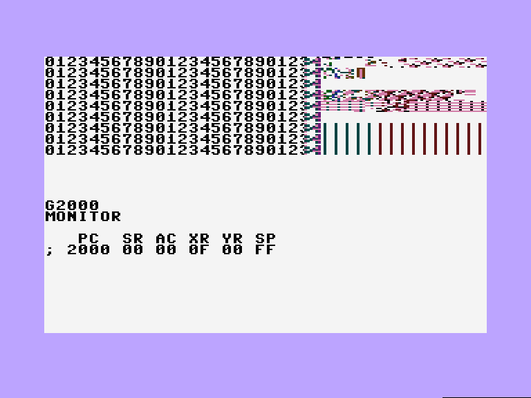
Those are the original picture (image on the left) and how it looks running my silly code (image on the right, please look at the real single problem: 2 black scanlines per char row which still are #$3b instead of switching to text -> #$1b):
 
Ok, let's talk about solving this problem, add your 2¢ now. If you're a C64 coder -> $ff06 == $d011, and no VIC-II tricks.
|
|
Posted By
Luca
on 2010-12-05
16:41:50
| Re: Vertical splitting
First addon by me.
It would be possible that I'll have to be forced to swap the two areas, and have the 15x25 bitmap area on the left and the 25x25 text area on the right.
Why this?
For two reasons:
- TLC pointed out that if you change $ff06 before $ff1e=#$b0, the badline will be avoided (all the consequences remain at now unsolved, how many cycles I'll have in that scanline, for example?)
- a badline occurs when the first three bits of $ff06 match the first three bits of $ff1d ($d012 on C64); if you (LDA+AND#$1f) $ff1d, ADC #$(2 < x < 7), ORA #$10 and STA$ff06 you can avoid the badline, but in order to do it before the end of the scanline you have to sacrifice the last part of your scanline; if you move the 25x25 text area to the right, you can use that area, reduced in the left side because of the bitmap->text area transition's garbage, and in the right side because of the latter problem we talked about.
|
|
Posted By
TLC
on 2010-12-05
18:08:16
| Re: Vertical splitting
You can't interrupt DMAs in any way. ...It's very simple: you can't get back to control once you lost it, until you're given it back (which won't happen in a middle of a line).
Also, I'd suggest arranging a theoretical experiment. Let's suppose you "can" interrupt a TED badline ie. DMA somewhere in the middle of a line. ...Then, you need to do the $ff06 write (4 cycles), and "re-initiate" the badline (4 cycles at minimum, +3 pending DMA cycles). Let's suppose you combine the two (since it's likely that you'd write $ff06 for both operations anyway). Now you have 7 character places (minimum) whose DMA cycles have been skipped, ie. whose character pointe/color or color/luma data is not updated / is corrupted. ...So even if you could break a badline, you'd still have to face some consequences.
Delaying the start of DMAs might help to arrange the mode change, and still maintain color+luma data fetch for the right side of the screen ie. the multicolor bitmap. Character pointer + color data fetch for the left side are unfortunately skipped (due to the skipped left part of the DMAs). Also, three characters after the position of triggering the DMA -- in this case, the first three positions of the bitmap -- will be "invalid" because of pending DMA cycles.
The most clear solution should be skipping DMAs completely -- with the consequence of skipping character pointer + color / color + luma fetches completely. That is, the left side shows the same rows as the first one (...or invalid data, if the first two badlines had been skipped), and the right side will appear in the colours + luma of the first row (...or, again, invalid colors).
...Or you can possibly avoid the whole fuss by implementing your character-based stuff on the multicolor bitmap... with the other benefit of not having to spend the whole screen in a busy loop.
Edit:
The $b0 value is not precise, I don't remember where exactly the checkpoint is (but all checkpoints that have something to do with badlines + pointer increments are past that point... loosely that value, that is). If you're on a line before a badline, take $ff1d & 07, add x>=2, put that to bit0..2 of $ff06 and you do all that _before_ the b0 point, the next badline will be skipped. You might possibly arrange a test where you'd only deal with badline skipping... won't take more than some ten rows (if you already have the cycle exact timing infrastructure). From that, you could conclude the "last" cycle that still fits.
Also -- notice that you could probably arrange your code to write $ff06 only once. The $b0 cycle is well past the point of where you intend to switch the screenmode.
Edit: ...Precisely speaking, that particular cycle is way "past" the character area, it's in fact at the end of the right sideborder.
|
|
Posted By
Luca
on 2010-12-08
11:24:59
| Re: Vertical splitting
It does not work in my case, dunno why 
Of course, avoiding the badline sets the next scanline at 65 cycles, I guess...and what about the 2nd badline?
I'm desperate 
|
|
Posted By
Rybags
on 2010-12-11
09:44:55
| Re: Vertical splitting
Just use Text Mode and change character sets every three character lines.
Problem there of course is you lose half the colours.
Alternatively... take advantage of the fact that in a text mode with just normal alpha/num characters, you can have a character set with 2 blank scanlines and still have the text looking normal.
Define the text character set such that the last 2 lines are blank and first 6 contain the alpha/num bitmap parts.
During badlines, just leave it in bitmap mode the entire duration.
|
|
Posted By
TLC
on 2010-12-11
11:14:26
| Re: Vertical splitting
Tailored something together today; you can find the pieces here: http://coroners.no-ip.hu/split . I hope 1.) the download works (tell me if it's broken, will work out something), 2.) it helps somehow.
The stuff has been coded in monitor, so there's no source file.
How does it work?...
1.) IRQ would fire somewhere before the first badlines.
2.) timing is stabilized.
3.) Wait until the first and second badlines go down. (That's mandatory -- else, there'd be no valid screen + color data).
4.) load 7 to X
5.) Some cycles before the character area of line #5, write ((X and 7) or $18) to $ff06.
6.) Wait
7.) Somewhere on the line (so that the write to $ff06 would happen before character #25 of the line), write ((X and 7) or $38) to $ff06.
8.) wait some, so that from 5.) to 9.) take exactly 65 cycles
9.) inx, if X is less than a reasonable value, go to 5.). (Reasonable value = number of lines to go - 7)
10.) cleanup; goodbye
It should be possible to optimize the process; however, the basic principle seems to work.
I didn't read and use $ff1d in this example; I chose to use a counter + a suitable start valueinstead, and incremented that counter with each scanlines. It should be equally possible to base something similar on $ff1d.
All in all, the only important point in this experiment is, that if you a.) use some suitable value for the low bits of $ff06, which is constantly offset from $ff1d's value by 2 or more -- , b.) set textmode some cycles before the character area would start, using the value of "a.)" as bits 0..2 of your value to be written to $ff06, c.) set bitmap mode at your position of the screen using the above value for bits 0..2 , then it should just work. As the value used here is constantly offset from $ff1d, no badlines would occur until the effect is stopped.
(Now, thinking over when I'm writing this comment, b.) is possibly unneccessary ie. the value which is used to set character mode might possibly just be constant, with no neccessary fiddling with its low 3 bits; but I haven't tried that).
HTH...
|
|
Posted By
Csabo
on 2010-12-11
16:30:24
| Re: Vertical splitting
TLC, you iz da awesomeness.
That is all.
|
|
Posted By
gerliczer
on 2010-12-12
08:00:28
| Re: Vertical splitting
Great indeed. I watched it in both YAPE and plus4emu. The attached screenshot must be from plus4emu because in YAPE the mode change happens at character boundary. Unfortunately i don't have suitable equipment to transfer the program to real iron so could someone else try it and tell us which emulator is wrong? For perfect emulation either IstvanV or Gaia has to improve his software.
|
|
Posted By
TLC
on 2010-12-12
09:22:19
| Re: Vertical splitting
gerliczer: neither I have a system up and running at the moment (that's why the code has been created in an emulator, at all, at the first place ); I'm in the middle of re-organizing stuff around me (let alone that I should seriously find some better use of my time now, because of university study "constraints"  ), so I wouldn't try that myself ATM unless absolutely neccessary. ), so I wouldn't try that myself ATM unless absolutely neccessary.
Yes, the code has been created using plus4emu; for Linux, plus4emu is native, whilst YAPE isn't (...under Wine, it runs fairly well, though).
|
|
Posted By
Gaia
on 2010-12-12
14:31:55
| Re: Vertical splitting
I recall there is a cycle delay in mode changes (FF07 etc.) which is not implemented in Yape (mainly for laziness reasons). Actually it is stated on the to-do list. I shall see if it's worth the effort though...
|
|
Posted By
Rachy
on 2010-12-12
17:29:49
| Re: Vertical splitting
Well done, TLC!
|
|
Posted By
siz
on 2010-12-13
08:06:49
| Re: Vertical splitting
Awesome work (again), TLC! Congratulations!
|
|
Posted By
Luca
on 2010-12-13
19:03:32
| Re: Vertical splitting
FUUUUUUUUUUUUUUUUUU! You did it, in a way I can't fully understand right now...but it works!
I passed the split.prg with to a disassembler obtaining a pseudocode where to play with. At the moment, I'm performing some little unsuccesful attempts in order to manage it, extract it from its IRQ and so on. I see there's a faulty first pixels row in the bitmap side, and dunno why I can't manage the colours in a straight way.
Anyway, this is a toy-ish attempt and I'll look further into this code, which now sems like magic to me.
Great job, thanks TLC! Keep an eye here because I feel I'll have some tons of questions about it
|
|
Posted By
Litwr
on 2010-12-15
08:57:55
| Re: Vertical splitting
I can't get anything from http://coroners.no-ip.hu/split. Is there any other link? pls...
|
|
Posted By
TLC
on 2010-12-15
12:26:13
| Re: Vertical splitting
Guys, thanks for your kind words  , well... The example routine really wasn't meant to be something extraordinal . The part which skips badlines is a pretty old trick, people have been exploiting that (...if not just for the sake of skipping badlines, then for FLD effects, which is the same league; you just need to do some wiggling of the $ff1f register) for long. The other part (cycle exact timing + mode change at some predictive point of a line) has already been exploited by Luca in his original code, as far as I can see. , well... The example routine really wasn't meant to be something extraordinal . The part which skips badlines is a pretty old trick, people have been exploiting that (...if not just for the sake of skipping badlines, then for FLD effects, which is the same league; you just need to do some wiggling of the $ff1f register) for long. The other part (cycle exact timing + mode change at some predictive point of a line) has already been exploited by Luca in his original code, as far as I can see.
Luca: the routine only depends on your timing routine at its "start"; the cycletime of the rest of the code is constant, ie. doesn't depend on anything but itself. Just make sure that first write to $ff06 (in the IRQ routine, of course) happens two or three characters "before" the character area /under the left border of the first non-badline of the visible screen (ie. the second visible line; the first visible line of the screen is a badline). From that on, the routine is strongly supposed to work just as it is.
You can't do anything with the first pixels row, that row is a badline (the second badline of the first two badlines of the screen), ie. it is needed, and it can't be broken in half. You can possibly edit your gfx so that that row is masked (black, or anything). The colours should be normal as far as I can guess -- with the exception of the fact that you have to make it with the set of colours set by the first row (as a consequence of skipping badlines; colour ram is never read, as long as the skipping of badlines is in effect).
Litwr: the host has been down for possibly half an hour or so (it should be back now)... sorry for the inconvenience.
|
|
Posted By
Luca
on 2010-12-16
05:22:03
| Re: Vertical splitting
Aaaah bitter surprise!
That way, setting, i.e., $ff14 as #$7f (Multi Botticelli) TED will assign the same colors in all the 24 next rows! Sadly, that way has no use, is a bigger limitation than using a charset compressed 4 colours picture instead
Edit: I tried to code a real tech-tech instead of a silly $ff07 wobbling logo. I had lotta troubles with badline, both in timing and in let it understanding I have to change $ff13 and $ff07 in badlines too. Result: I succeded, but only because:
- I started timing it up from far away ($ff1d=#$01, of course $ff1c=#$fe otherwise it happens two times a frame);
- I started exactly from the very first badline.
...and I'm scared thinking about the time I would need to move it from the upper left corner, where I located it :/
|
|
Posted By
TLC
on 2010-12-16
13:33:15
| Re: Vertical splitting
That's actually no more limiting than using character mode + 4 fixed colors (...it's essentially similar; ie. you can use only 4 colors in practice, too), ...yeah, it's slower, due to assigning the CPU to do the trick (whilst charmode needs no tricks). I do remember having told some doubts whether the skip-badlines trick will do it for your effect's purpose, though.
On badlines, you only have about 22 cycles to do all of your tricks (with one or two cycles more if you're lucky). That's pretty limiting indeed...
|
|
Posted By
MMS
on 2010-12-16
15:02:45
 | Re: Vertical splitting
Is it true, that Plus/4 has more troubles on the badlines, than C=64?
|
|
Posted By
TLC
on 2010-12-16
15:34:26
| Re: Vertical splitting
MMS: it "depends" (ie. on what you call "trouble").
It has twice the number of badlines (2 per character row, instead of 1).
Some effects (that you'd base on some wiggling around badlines) don't work on Plus/4, due to small differences. Ie. delaying badlines will "move" the screen of the C64 (because the counters that address the screen memory will be affected by the number of skipped character positions); on Plus/4, the rules are slightly different, so this trick won't work.
From the other hand, the badline logics of the TED is slightly more flexible than that of the VIC (simply put, there are more registers to be interfering with ). Also, the two badlines have own badline conditions, respectively. Those give slightly more possibilities.
One important factor, there's no "FLI bug" on the TED, which affects all forced DMA effects (FLI et. al) on the C64.
|
|
Posted By
Luca
on 2010-12-16
19:42:38
| Re: Vertical splitting
I remember that TLC has been a sort of pioneer about FLI mode on Plus/4
I really did not expect that strong limitation: the gain in having a real bitmap with its own color map is, of course, to have several colours, the malachite's graphic you can see in my specimen is a good example. Following my method, I have no troubles in the bitmap side, but I'm not able to avoid the two badlines, even when perfectly timed with the screen, as I shown. With your method, badlines are off, but even assigned $ff14 before, valid both for text and pic, the colors must be those in the very first row (MultiBotticelli: $7800-$7827/$7c00-$7c27).
How sad, I must declare defeat on the higher target
If I wanna display an effect+a bitmap, the effect must lie in the bitmap itself. Otherwise: 1, accept badlines (haaaard...); 2, reduce colors in the bitmap (but more than 256 chars and save of text area's charset); 3, use the same charset for both compressed graphics and effect.
Edit: of course, a STX $FF06 in the last 4 cycles available before a badline occurs does not work because $FF1E >> #$B0, right? :(
|
|
Posted By
TLC
on 2010-12-17
08:06:59
| Re: Vertical splitting
Nah,... as you see I didn't invent that "myself" but I learnt how to do that by inspecting someone others' code (Mucsi, to be precise). ...Okay, looks like I'm gonna chit-chat some, please skip if uninterested . ...So, the first FLI code I've ever seen on Plus/4 has been Muffbusters' part from Compy Xmas (ie. Compy Xmas'90). By then, I had already known how the effect should work in principle, but not from my own experience; I knew the "how"-s and "why"-s from a friend (József Virág a.k.a Hellish Boy who also did some gfx-artwork for my early demos) who had been doing C64-related scene activities; yet, I couldn't translate that knowledge to Plus/4 code at the time, I was just not experienced enough (...and C64 and Plus/4 FLIs, although similar in principle, do also slightly differ from each other). ...As you can possibly see, not even Mucsi knew exactly how Plus/4 FLIs ie. TED badline logics really worked, he coded something that looked "likely" to be "the" FLI effect of the TED -- I would make a huge bet that he based his routine on C64 experiences, judging from the routine itself -- , wrote some efx on top of that and that was all, that's what we could watch in their part from Compy Xmas. Neither did I realize that this original FLI routine was not "everything" possible with the TED, ...and I've been also hindered by some boundary conditions, ie. no earlier had I any Plus/4 scene contacts than late August/early September of 1991, ie. I couldn't really have hot Plus/4 scene stuff before but just with huge latencies; I remember I didn't have Compy Xmas before late spring/early summer of 1991 (which means approximately half a year of delay).
My FLI Editor was created during the autumn of 1992. ...At the time I was slightly down with scene contacts, because my OC-118N drive had given up the fight, it was irreparable, and I couldn't afford buying a replacement. The stuff has consequently been created with just a datassette at hand, and in monitor (and at the same time, my possibilities to swap stuff with people greatly dropped). Little did I know about more possibilities of FLI (I didn't know how it worked "precisely"), thus the "classic", 1-line FLI effect supported by the editor (which is, admittedly, basically useless for hand-pixelling gfx -- but I didn't know that fact at the time, nor the other fact, that "1-line FLI" was not the ultimate end of possibilities from FLI effects). But I know that MC has already been experimenting with FLI effects at the time, and I suspect he must have already known much more about how things "work", probably for the first time in Plus/4 scene history. This is supported by the fact that Legend of MC and Fatal Mirror already exploit tricks that force just either or the other of the two badline types -- consequently, he must have already known how to force the "first", "second", or "both" badline conditions, as early as in 1993 (or even late 1992).
I did create a 2-line FLI effect just the next year (...it was surprisingly easy to do, after all), when I wrote the original version of the old PC-C= gfx conv stuff at the PC programmer course that I was attending at the time. But not even that one implied "deep" knowledge of how the TED badline infrastructure worked; it was just a "copy" of what/how the TED itself did, cautiously avoiding "life-threatening" situations (like forcing a badline condition on every lines, whose result had already shown how things should "not" be done).
Researching how the whole badline logics of the TED worked came much-much later. Maybe early 2004, we discussed some things about deep TED inners with Gaia and I also did some tests on the real iron, bringing a couple of checkpoint positions + researching how "really" the TED badline logics worked. I don't have that information "formalized" (...at the moment, I'm not even sure that I have the old e-mails and sketches at all, as I lost my e-mail boxes once or twice in the meantime; Gaia once kindly collected and sent me the majority of e-mails back, but I'm not sure that I have that pack; at least, I couldn't find it right away). Yet, Yape still has that information "collected"... (with possible modifications and corrections; at least I don't know details from about the time I stopped contributing to it).
-- Chitchat mode off --
It's the badlines that read color and luma memory; so you either let "badlines" happen and have TED color ram reads (which is done during that time), or you skip badlines _and_ TED color ram read altogether. ...Maintaining color ram reads while skipping badlines is impossible.
Maybe, you can do the following trick:
-- Reduce your gfx's colors, so that it fits into the 3+1 schema (ie. 1 color per character place, 3 colors for the whole gfx). Make sure the "1" colors are from the lower 8 Plus/4 palette colors. That way, your gfx theoretically fits the limitations imposed by MCM character mode.
-- Allocate "enough" number of characters for your effect (ie. the left side of the screen), allocate the rest of the characters for the right side ie. the gfx.
-- "Design" a schema of characters on the screen ie. make a map of how the screen will be filled by characters. One set will certainly not be enough -- no problem, you'd handle that by swapping charsets ($ff13) using raster IRQ.
-- If you have an idea of how the map looks like, write a routine that packs your gfx into the respective characters of the sets. You'd also generate a colormap, ie. the color memory content of your gfx.
...The "pack" routine might be tricky at first sight, I bet I'd certainly spend some time fiddling with a routine of that sort. (But the method is possible).
That way you could have hi-res mode for your effect, avoid most of the heavy-lifting imposed by the whole-screen-high raster routine needed by the original mode change method, and still maintain some chance for a more-than-4-colors malachite gfx on the right side of the screen.
Yeah, writing to $ff06 at that position would probably not work, but I don't know for sure; as said I don't remember the exact positions and exact badline logics ATM.
|
|
Posted By
Luca
on 2010-12-17
19:54:23
| Re: Vertical splitting
This is for sure the most interesting topic I've read on Plus/4 World since years, thanks TLC and all of you guys.
To whom is skilled enough, I strongly suggest a serious editing session of the FLI chapter in the Plus/4 Encyclopedia, with historical notes, different approaches, names sourcecodes and all the rest.
Another related question: in any case of delicate timing against badlines, would be possible that a joy/key check using $FD30/$FF08, even if far away in $FF1D timing from, say, my tech-tech, would affect the precise timing of scanlines/badlines, producing artifacts?
|
|
Posted By
TLC
on 2010-12-18
15:50:06
| Re: Vertical splitting
Encyclopedia:I guess I'd leave that to someone else; I don't seem to have all cards in my hands.
Timing: if you inspect the first ten or so rows of my IRQ code, you'd notice that it delays some variable number of cycles, depending on a value which is derived from $ff1e. This part is going to accomodate for any random delays introduced by instructions executed in the moment the IRQ happens. There's no way to interfere with that code from the main program, ...well, unless you disable interrupts sometimes ie. do something nasty. So the answer is: the raster remains stable (ie. cycle exact) as long as you don't disable interrupts in your main program (...which is unlikely, as I guess). You can simply copy the logic of that routine -- only the number to be subtracted, and/or the number of LSRs would need to be changed.
Addendum to yesterday's chitchat: I watched some demos today, and found out that EDC's Imagine already contains pretty tough FLI effects, coded by MC. I didn't check these very closely, but as it appears, they lack the luma-chroma "mixing" effect of early FLI effects, thus, they're 2-line FLIs, or at least 1-line FLIs where only the luma data would be refreshed every lines. Either way, this shows that back in the summer (or early autumn) of 1992, MC did already know more about FLIs than anyone of us did. ...I couldn't track down the exact release date of Imagine, but it must have happened somewhere around September, 1992. ...Too bad, knowing more about that could have spent me writing the FLI Editor stuff the way I did. It's especially a pity, as I remember MC visiting me that summer and showing me some experimental FLI effects, when he came to Dombóvár to meet some of his friends.
|
|
Posted By
Chicken
on 2010-12-18
18:39:19
 | Re: Vertical splitting
SCF got it somewhat right in A Trip. So he probably knew that he could only refresh the luma RAM? I've never examined this closely, though. Maybe the black part at the left side of the screen "hides" some timing problems? Anyway, he doesn't have the "mixed" color like those other early FLI effects TLC mentioned above.
A-System did a "Luma-FLI" in To Be Ashamed in early 1991. Back then I didn't see this demo. Though, it was announced in some other production. Obviously, they were inspired by "Charlatan" by Solomon/Beyond Force and claimed to have done 40 raster splits On a side note, Pit (or Ran) mentions in the scroll text that Ceekay ripped their FLI code.
I also liked Toxyc's Hard Death (coded in Spring, 1993) which featured an effect he refered to as "ECI split" but as far as I can tell without checking the code is also some kind of "Luma-FLI".
|
|
Posted By
Luca
on 2010-12-19
10:49:51
| Re: Vertical splitting
I added this piece of code to my tech-tech, after the scanlines/badlines stuff and before the $ff13/$ff07 resetting, and I got a better stable performance:
I_2080	LDA $FF1E	; Horiz Scan
	SEC
	SBC #$96
	LSR A	; div / 4
	LSR A
	STA V_208B + 1
V_208B	BCC B_208D + 1
B_208D	CMP #$C9
	CMP #$C9
	CMP #$C9
	CMP #$C5
	NOP
	LDX #$05
B_2098	DEX
	BPL B_2098
TLC can you explain this one deeply? It's very very interesting, have to say, especially the #$c9 slice where you can wait for either X cycles or X+2 cycles...
|
|
Posted By
TLC
on 2010-12-19
12:13:26
| Re: Vertical splitting
Chicken: thanks for clarifying this... I did know about SCF's routine, but not the other ones. ...I lacked scene contacts before early autumn, 1991, and I lacked a floppy drive for about a year from early summer of 1992. Even speaking about A Trip, I didn't know about the existence of that routine before someone, most probably Gaia showed that to me once, as the demo with the first ever FLI effect on Plus/4. ...SCF must have been a genius; he did pretty tough TED tricks as early as in 1988...  That seem to raise a question, though... ie. "how exactly" these guys might have known what they were doing. AFAIR, the classic, "mixed color/luma" effect is pretty straightforward for someone with previous C64 experiences, but the other ones (let alone "luma only" and "chroma only" FLI tricks) are certainly not. That seem to raise a question, though... ie. "how exactly" these guys might have known what they were doing. AFAIR, the classic, "mixed color/luma" effect is pretty straightforward for someone with previous C64 experiences, but the other ones (let alone "luma only" and "chroma only" FLI tricks) are certainly not.
Luca: This is a "cycle exact timing" routine.
As you know, the CPU doesn't interrupt instructions before it takes an IRQ. At the time an IRQ hits, the CPU might be at the end of some instruction, but it might also be at the first cycle of executing some long instructions, ie. an INC abs,x (7 cycles) or possibly an illegal code (indirect indexed read-modify-write instructions, worst case, 8 cycles, if you use some of them). That imposes 0-7 cycles relative latency, at the point the IRQ routine is given control. The goal is, to provide a "cycle exact" startpoint in the IRQ routine, ie. that from some point and on, the initial delay won't play a role.
So...
-- Read $ff1e
-- Subtract #$96.
-- Divide it by 4.
Comment: my routine was coded with redirecting the ROM IRQ vectors in mind (ie. $0314-$0315). The position where the IRQ hits is (AFAIR) line #02 (still under the upper border, no badline, line timing is similar to the character area lines). Control is taken in a minute where the horizontal raster counter is at least #$96, or more. ...Determining that value has been completely experimental (...didn't go further with coding at the first time, but dumped values that the routine could read at this moment, and determined the least one, which was #$96). The CPU gets single clock around this place (for this and a few more cycles). In one single clock cycle, $ff1e is incremented by 4. Consequently, one single clock cycle delay increments the result read by the LDA $FF1E by 4.
If we take that number, subtract the base (in this case: #$96) and divide the result by 4, the result will be the relative latency that the IRQ routine collected until this point.
STA foo
foo = *+1
BCC *
CMP #$C9
..
..
CMP #$C5
NOP
This is some self modifying code with a delay line.
The STA stores the number of previously calculated cycles in the operand of the BCC instruction.
As the previously divided number has been a multiple of 4, the result of the LSRs is C=0. Thus, BCC is taken.
The BCC will skip "its operand" number of bytes.
The CMPs and the NOP form a delay line. If you jump in at an even address, the instructions taken are a number of 2-cycle CMPs and a NOP. If you jump in at an odd address, the instructions taken are a number of 2-cycle CMPs + a 3-cycle CMP at the end (ie. CMP $EA). All in all -- with each address forth, delay is one cycle less. Since the parameter we use here, is the number of cycles "lost" until the point of receiving control, with each "lost" cycles we delay one cycle less. In other words, if the initial number that we calculated is 0, then the whole delay line is taken. If it was 1 (control taken was late by 1 cycle), one position less (ie. one cycle less) of the delay line is taken. At the end, wherever the control was taken initially, the delay at that point will be constant.
The rest is constant delay, nothing special.
If you intend to do something similar in your code, you have to pay attention to where your IRQ code gets control (ie. the least number that you read from $FF1E at this place), and the clock mode of the CPU around this place (ie. for double clock mode, a divide by 2, not 4 is needed).
That's all I guess...
|
|
Posted By
Luca
on 2010-12-19
13:15:07
| Re: Vertical splitting
Brilliant piece of code!
As I told before, I used it after the tech-tech and before the joystick reading routine: no artifacts, no bugs, worked for me.
|
|
Posted By
TLC
on 2010-12-19
16:22:08
| Re: Vertical splitting
Wasn't my invention AFAIK... or at least not exclusively. I did code "cycle exact" timing routines back in 1992 or 1993... but not this way... those were all "double interrupt" based ones. Later it "cleared down" to this simple form. AFAIK similar routines are widely utilized.
You seem to be lucky. ...Unless you also redirected the ROM IRQ vector, and set your raster interrupt position to a non-badline character area position, that is...
|
|
Posted By
Luca
on 2010-12-19
16:42:37
| Re: Vertical splitting
Well, usually when I try a slice of code, I do not use any IRQ, the code goes straight as main with of course some $ff1c/ff1d managing, and will be placed in the right machine time once used for real...yes I've been lucky this time
|
|
| |
Copyright © Plus/4 World Team, 2001-2025. Support Plus/4 World on Patreon |