Posted By

SukkoPera
on 2023-02-06
03:39:38
|  Re: Solder's SIDcard Replica Re: Solder's SIDcard Replica
Well, it took some time but I was finally able to test the older 4520 chips and the card works perfectly with them!
Thus, it was finally time to make the project public and release the board: the project page is available here with all the design files and docs. There is also a link to get the boards made by PCBWay, but I have a special offer for all people of this forum: if you want a couple of PCBs, you can get them for just the shipping costs, just write a PM to me! 
Thanks to all those who helped and enjoy!
@Frenetic: Now it's also time for that email! :)
EDIT: I took scope measurements of the different 4520 chips:

You can clearly see how much faster (~90ns on the rising edge, even ~130ns on the falling edge! Vih=2V, Vil = 0.8V) the 74HCT4520E is (yellow) wrt the older SGS-Thomson CD4520B (white). Blue is SID /CS and pink is C16 PHI2.
EDIT 14/11: I spent the last few days perfecting the card. There was some annoying hissing and whistling in the background which I managed to eliminate after maaaany attempts by replacing R8 with a 3.3 or 4.7 ohm resistor (was originally 1 ohm). This solves 90% of the problem with 8580 SIDs, while some hiss still persists with 6581s, which can be totally eliminated by using 100 uH for L1 and 130 pF (yes, an uncommon value but worth it!) 100pF for C15. These values also help with 8580s but the effect is far less noticeable.
These values will be the default in V2 of the card which we should be testing soon and which also has a few more modifications to improve the quality of the audio output (and more!). This is also why I still haven't shipped any of the cards I promised, as I plan to send V2 cards. Hope the extra wait won't be a problem!
I have also prepared a comparative audio test so that you can judge the output quality for yourself: it opens in Audacity, use the Solo buttons and enable one track at a time:
- Top track is from a CAE card with an 8580 SID.
- Middle track is from a ReSeed V1 with R8=4.7ohm with the very same SID as the CAE track.
- Bottom track is from a ReSeed V1 with R8=4.7ohm, L1=100uH and C15=130pF with a 6581 SID.
The tracks are synchronized, so you can switch while listening. Also try panning one on the left side and a different one on the right side for some nice effect :).
Enjoy!
EDIT 04/02/2023:
So! I've been building and testing V2 of the SIDcard. The focus for this version was on reducing the output noise. Following is a list of the changes:
* New component values for the step-up voltage regulator: The values of some components were fine-tuned (again) in order to place the switching frequency of the step-up voltage converter way out of the audio band. These new values can also be retrofitted on a V1 board and will improve things dramatically (See V1.1).
* Alternative voltage step-up module: Cheap step-up voltage boost modules can now be used instead of the TL497-based circuit. Such modules, which can be easily sourced from Chinese portals, are much more modern and use a higher switching frequency, resulting in (near-)zero switching-induced noise. Using them also speeds up the assembly process, as many components can be skipped.
* Linear Regulator: If you are really paranoid about switching-induced noise, you can use the above alternatives as a first-stage voltage regulator and then make a second stage through a linear regulator, which should "eat" any remaining noise and provide the SID with very stable power.
* Separate grounds: A separate audio ground plane was introduced and connected to the signal ground plane through a single ferrite bead, preventing noise from spreading from the latter to the former. A second ferrite bead was inserted on the incoming +5V power rail in order to make it cleaner.
* Alternative BJT footprint: An alternative footprint for the output amplifier transistor was added, allowing for the mounting of the 2SC1815 BJT used in the original C64 audio circuit.
* SID clock delay circuit: This allows use of CD74HCT4520B chips in place of the CD4520B.
* Clock divider reset: Makes sure the SID clock always has the correct phase upon startup/reset.
* Short-circuit protection: In the original Solder design, a short-circuit can happen on the joystick port if it is written to. Series resistors were added in order to avoid this situation.
It works really well. The very last thing I am testing is the paddle/mouse/analog joystick circuit. I have been playing a lot of Arkanoid +4 Analogue Edition (Nice music, BTW!) and I found this could be improved: Solder used 100 ohm resistors in series with 3.9nF caps in the circuit. Comparing these to the C64 circuit suggests that the resistor was introduced to approximate the internal resistance of the CD4066 switch that the C64 uses to switch between the two joystick ports, while the capacitor is larger than the 2.2nF used in the original circuit. I found that these values greatly reduce the usable range of the paddles, meaning that the maximum value is reached at 3/4 of the whole paddle rotation. Did anyone else notice this? I tested with 2.2nF and it looks like that allows using almost the full range of the paddle. That makes it mostly OK but I will try lowering the resistor as well. I have also noticed that the 6581 SID requires even lower caps (1.8nF), so I think I will remove those values from the silkscreen and make them depend on the SID model.
Another oddity is that I had left the 3 higher bits of the joystick register floating, as I didn't have the space to pull those high when I added the short-circuit protection resistors. This shouldn't be a problem, but with Luca's help we found out that Solder's Joystick-Testprogramm detects fire button presses by checking if the read value is > 15 rather than checking whether bit 4 is set, which means it detects spurious fire presses. I believe this is a bug in that software (and Luca has already provided me with a fixed version, thanks a lot!), but anyway I will also fix that before the final release, just in case other games have the same bug.
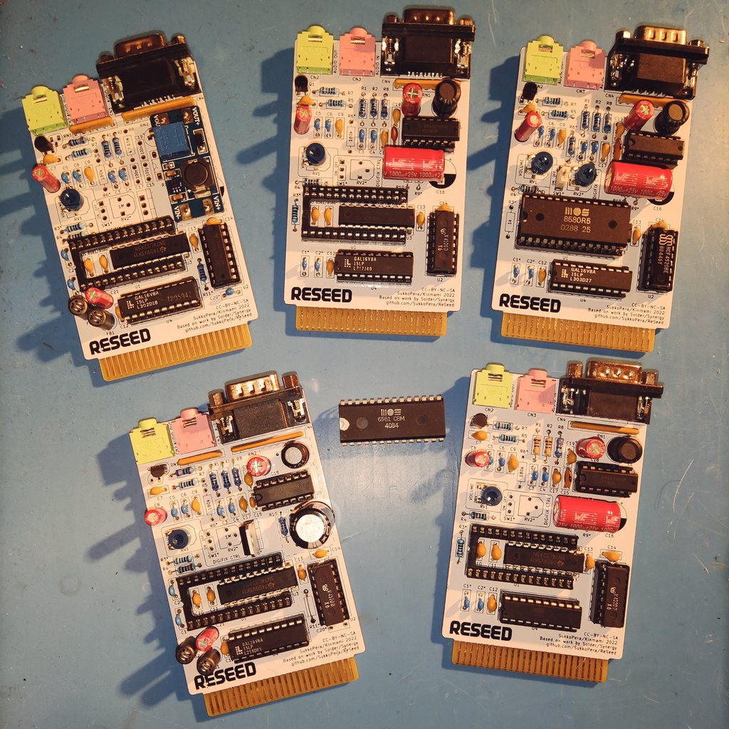
The two cards on the left are V2, the rest are V1.
I have also released V1.1, which is just V1 with the BOM updated with the changes I had already announced which dramatically reduce the output noise. Note it still has the 3.9nF cap in the paddle circuit though.
|