| Posted By

SukkoPera
on 2022-08-24
07:32:53
|  Solder's SIDcard Replica Solder's SIDcard Replica
I am working on replicating Solder's original SIDcard. I know there's already a better evolution of it around, but my own will be Open Source, following Solder's intentions from the era.
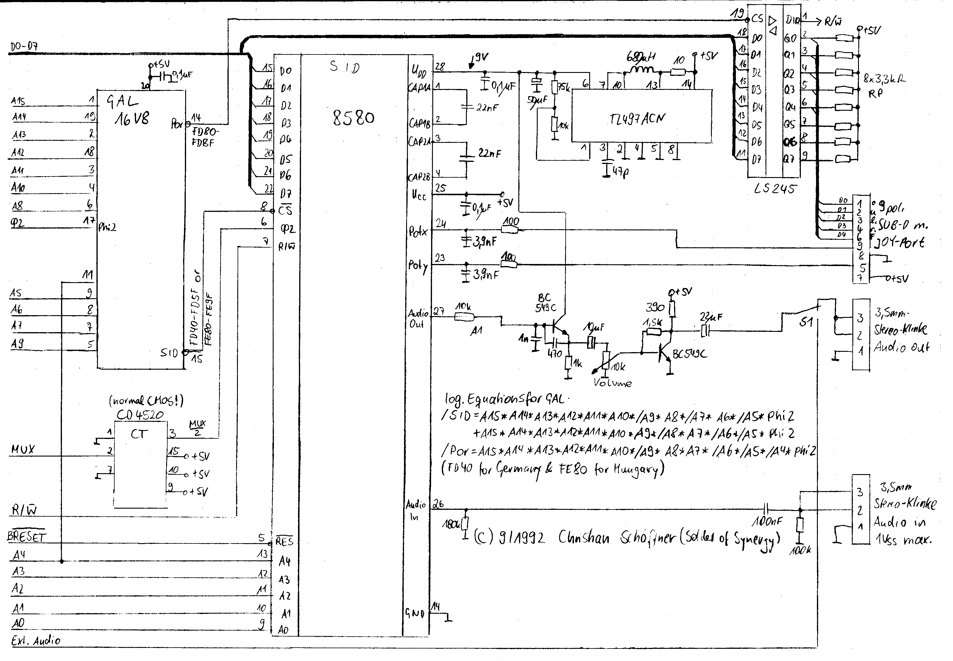
I have already had the first prototype PCBs produced. The design (and look) closely follows Solder's original schematics. In order to make sure that the schematics were correct, I also followed the tracks on a close-up picture of an original card kindly provided by Luca. I have already followed this process for quite a few other boards (way bigger and more complex), so I am pretty confident that the design is correct.
I am testing with the "Ninja 3" demo from disk 1 of the 4-disk package Solder was distributing with the cards he used to build, but unfortunately my card is not sounding correctly (the demo sounds fine on emulators). There is a lot of what I can't really describe any better than "digital noise, skips and glitches". I have already built two boards with two different SIDs and tested them on two different C16 machines, with different 64k RAM expansions, different power supplies, etc, but the problem persists. I have also used different JED files for the GAL: one I found around (GAL-SID.jed) and another one I compiled after just rewriting the equations myself, but to no avail.
I think I have just nailed down the issue though: Solder's design generates Phi2 (the clock) for the SID by dividing the MUX signal by 2 through a CD4520 binary counter, obtaining an ~886 kHz clock (the way he wired the counter makes the halved signal switch on the falling edges of MUX, this is definitely intentional):

This is lower than the frequency the SID is clocked at on the C64 and is the reason why everything has a lower pitch on the SIDcard, but it is not the problem per se. The problem is that, according to the original SID datasheet:
Phi2 also controls data transfers between SID and the microprocessor. Data can only be transferred when Phi2 is high.
This cannot be guaranteed to happen with the way Phi2 is being generated, and in fact I easily found moments where the SID is selected (SID /CS in blue) but Phi2 is low (pink):

Now, I am using a CD74HCT4520E for the binary counter, which is probably different than what Solder was using in the cards he produced, but could this really be the cause of the issue? I'll try and hunt down the "correct" chip, but I really can't see how a different chip would avoid this issue.
I would be glad if anyone has any hints  . Thanks anyway! . Thanks anyway!
|
|
Posted By
gerliczer
on 2022-08-24
01:53:46
| Re: Solder's SIDcard Replica
My memory somehow fetched from its foggy depths the advise never to access Solder's SID-card at anything but single clock ($FF13 bit 1 = 1). But I have no idea how much truth there is to it.
|
|
Posted By
siz
on 2022-08-24
05:04:38
| Re: Solder's SIDcard Replica
@gerliczer: as far as I remember that was true for the first prototypes but got solved later.
@SukkoPera: deriving SID clock from MUX was definitely intentional to avoid SID CS to be active when the address/data buses are not valid. If You don't do this You will definitely end writing wrong values to SID (or missing writes) that results in the exact problem You described.
(BTW this is the same problem we have with SID emulation of SideKick)
|
|
Posted By
SukkoPera
on 2022-08-24
05:37:31
| Re: Solder's SIDcard Replica
Thanks for your contributions!
@siz: Ok, I understand, but the clocking circuit on my board is currently 1:1 with Solder's schematics. Maybe such schematics are older and do not correspond to the working boards?
Is there anybody with a working board from Solder and a continuity meter who has some time to do some checks for me? Or maybe who would kindly lend me their board?
(I wanted to publish my own schematics but I had some issues in making a decent PDF, I will try again tonight.)
|
|
Posted By
MIK
on 2022-08-24
09:02:30
 | Re: Solder's SIDcard Replica
Also check your power supply or try another just incase as the official C16 ones are known to drop off on power over time, (due to age and poor design). Pressing play on the tape unit may also show different results as it sucks even more juice out of the power adapter.
|
|
Posted By
SukkoPera
on 2022-08-25
02:58:36
| Re: Solder's SIDcard Replica
Yup, already done that: I have tried two different PSUs (none of which original) and even checked the voltage levels.
@gerliczer might be onto something though: I have just had some fun with a Logic Analyzer and I think I can say that all the "bad" SID accesses happen during double clock periods .
EDIT: No, not really
So if there is a hardware fix for this, I guess it must have been found after Solder drew the schematics that are around.
Capture file is available here if anyone wants to have his share of fun ;).
EDIT: Here, in turn, is a recording of what I'm getting out of my card in the best case (more on this later). This is using a SwinSID Nano so don't be too fussy about the SID part itself :).
|
|
Posted By
gerliczer
on 2022-08-25
01:56:02
| Re: Solder's SIDcard Replica
OK. So, how does it actually look now? Your edit of your latest post got me a bit confused. Does it have misaligned bus cycles or not? Did you make the recording in single clock or dynamic (twiee interspersed with single) clock? If it does not interfere with SID what does?
|
|
Posted By
SukkoPera
on 2022-08-25
03:04:41
| Re: Solder's SIDcard Replica
Yeah, sorry, I was adding/editing things as I found them out. I'll try to recap:
The first image in the previous post suggests that bad SID accesses always happen during double clock periods.
But the card did not always sound the same. Sometimes it would almost not sound at all. Initially I attributed this to bad contacts but then I made another capture and noticed that when this was the case, almost all the SID accesses were bad.
So I thought: maybe the initial state of the counter (i.e.: clock divider) is random and if it starts at 1 most SID accesses will be misaligned and just a few will be correct, exactly opposite to the situation I had seen before.
I had already thought of connecting the /RESET signal to the counter during PCB design but I hadn't done it because the counter wants an active-high reset. But then I noticed the GAL had a few unused pins, so I quickly made an inverter out of two, added some wires and started resetting the counter with the whole machine. This *seems* to avoid the bad case and to always put the board in the "only a few" misaligned SID accesses.
The recording was made after that, but it should basically correspond to the case shown in the first image of the previous post, where a SID read and subsequent write will result in one of them being misaligned when done during double clock periods. I haven't made another capture after the reset fix but I can do it tonight.
So something more must be required on the HW side, as I would expect any care that should be taken in SW to be already implemented in the Ninja demo (but I also tried another demo and even the SIDcard version of Lykia, they all sound the same),
Is there a way I can disable the dynamic clocking before running the demo?
|
|
Posted By
gerliczer
on 2022-08-25
09:36:55
| Re: Solder's SIDcard Replica
I can describe you an annoying, one shot method. Assuming that the drive has the disk inserted:F2,*,Return
mO,Return
A111A JMP$800A,Return
Return
G1012,Return
mO,Return
A1090 JMP$800A,Return
Return
G1010,Return
mO,Return
A4012 LDA#$52,Return
Return
G4800,Return If it needs to be run just for a few times it may be bearable.
|
|
Posted By
SukkoPera
on 2022-08-25
11:23:27
| Re: Solder's SIDcard Replica
Thanks, I will try it tornight and see if it helps.
In the meantime, could anybody with a working SID card from Solder, a multimeter in continuity mode (beeeeep!), and 5 spare minutes help me, checking if the following connections match their board? Please only pay attention to the starting and ending points, the routing might be a little different:

These are all as seen from the top of the card, i.e.: the side with the components.
|
|
Posted By
Chronos
on 2022-08-25
14:39:30
 | Re: Solder's SIDcard Replica
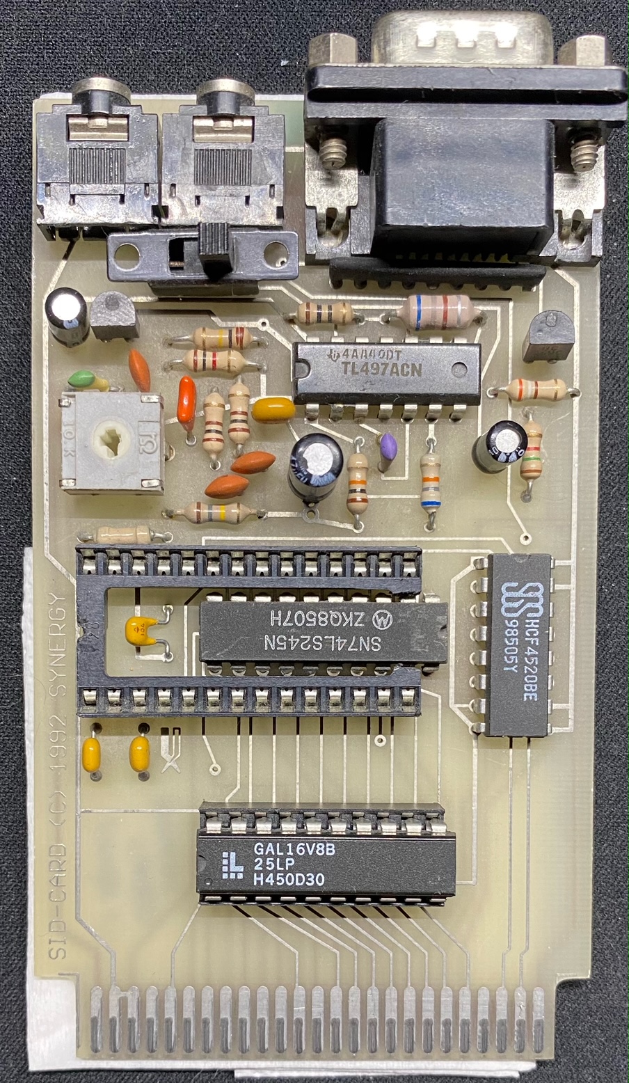
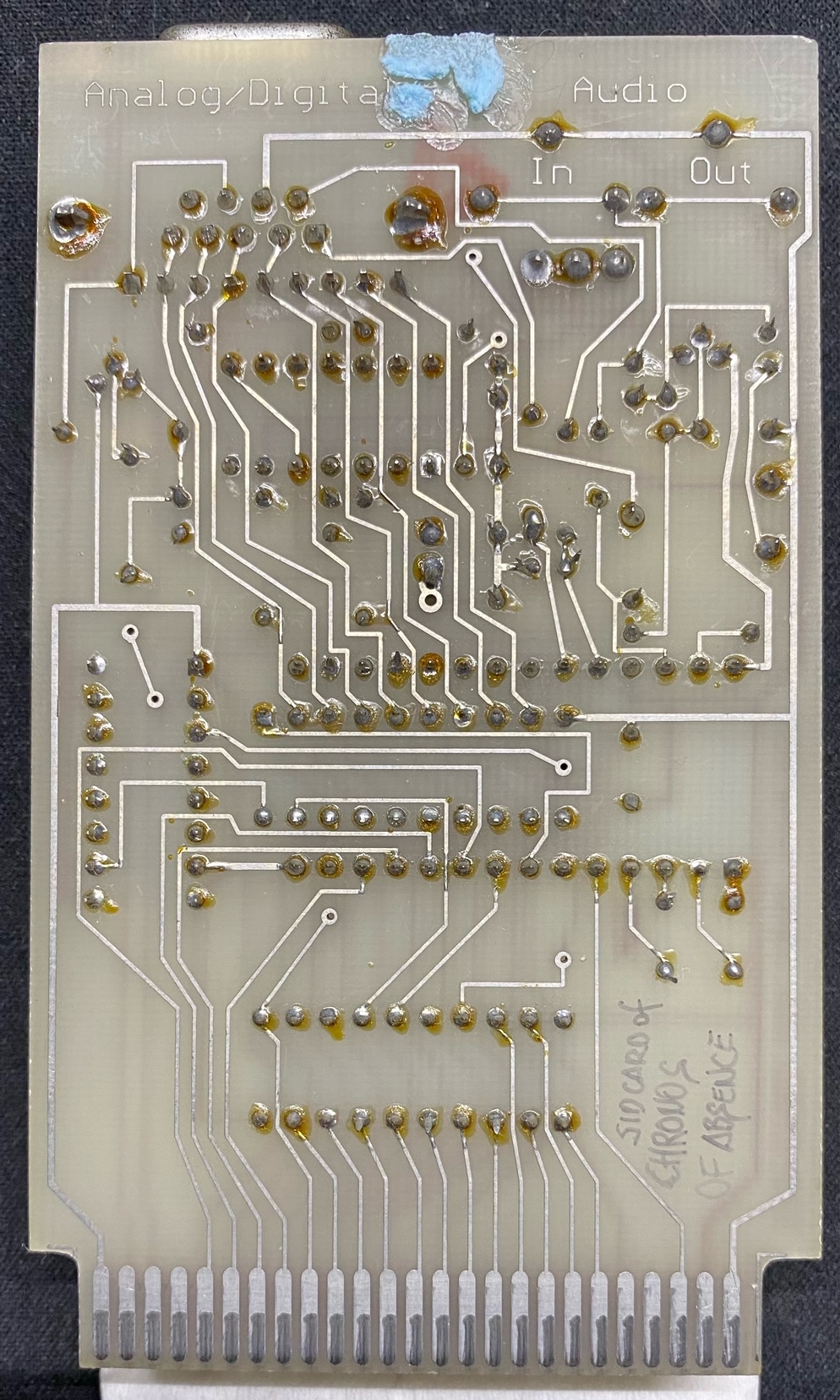
Dear Sukkopera! i own a solder card and a multimeter too  sooo: sooo:
1. yes
2. yes
3. yes
i can do pcb porn photos if you need them :D
front
back
|
|
Posted By
gerliczer
on 2022-08-26
01:37:17
| Re: Solder's SIDcard Replica
@SukkoPera: That layout is definitely not something based exactly upon Solder's original schematics.
|
|
Posted By
SukkoPera
on 2022-08-26
04:43:23
| Re: Solder's SIDcard Replica
First of all let me demonstrate what the "reset hack" I introduced above does. When the board starts up "correctly", this is what we have:
Pay attention, in particular, to SID PHI2 (yellow) being in phase with C16 PHI2 (orange): this makes SID accesses correct (at least those in single-clock periods) because the GAL asserts the SID /CS (green) on the rising edge of C16 PHI2 (address valid), and at that time SID PHI2 must be high in turn.
But sometimes I guess the counter will start up at an odd number, which results in SID PHI2 being shifted by 180 degrees and getting in counterphase with C16 PHI2:
When this happens, all SID accesses will be bad, except those made during double clock periods that would be those we are trying to get right in the normal case . The reset hack makes the counter always startup at 0, making sure that the correct SID PHI2 is being generated. I am not sure if the older 4520s have a circuit that guarantees startup at 0, but in any case this modification shouldn't hurt.
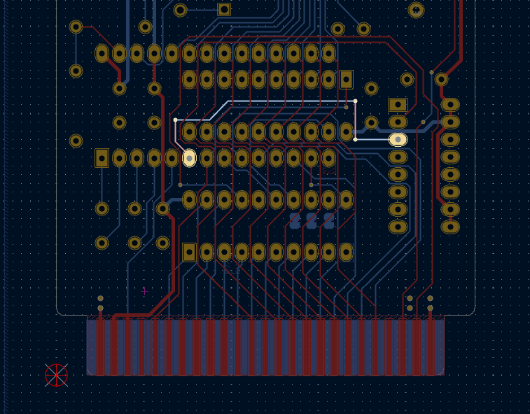
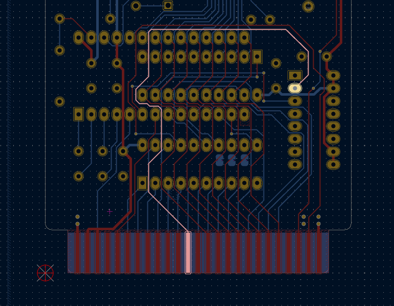
@gerliczer: Why do you say so? I can guarantee that the layout is very close to Solder's original. There are a few deliberate changes, but they either do not come into play at this stage or cannot hurt (we added a decoupling cap per chip, for instance). Besides that, you cannot really see the changes from the screenshots above, eh eh  . Don't be fooled by the routing being different, that was forced by needing to make the board less than 10cm tall (for manufacturing costs) and by the introduction of a ground plane. . Don't be fooled by the routing being different, that was forced by needing to make the board less than 10cm tall (for manufacturing costs) and by the introduction of a ground plane.
Before we did any changes, though, we made a version that was 1:1 with the schematics and routing, at least as much as I could guess from the pictures Luca had sent me. We didn't get that one manufactured, but it gave us confidence that the schematics we had redrawn were correct:
There was only one point where I could not see exactly where each track went as there were 3 close tracks going under a the SID socket. I sorted that out with the schematics of course, but a small doubt kept lingering and that is what I asked to check above, so thanks a lot to Chronos for that!
Now that I am 100% sure that the layout is correct, I'll keep digging. Still haven't had time to try the "force single clock" hack though.
BTW, thanks to everybody who's contributing, your help is much appreciated!
|
|
Posted By
gerliczer
on 2022-08-26
05:52:22
| Re: Solder's SIDcard Replica
Because I'm apparently blind. I managed to completely miss the 245 in the top right corner. 
|
|
Posted By
SukkoPera
on 2022-08-26
10:56:50
| Re: Solder's SIDcard Replica
Oh, I see . The 245 is only used for reading the digital joystick buttons though, it wouldn't hurt the audio part even if I hadn't included it (and in fact I haven't mounted it on one of my test boards).
I think I have found the culprit! The 4520 used on Luca's board was produced by RFT electronic (in East Germany?), here's its datasheet:

Notice the propagation time (Verzoegerungszeit): 560 ns (max)! The 4520 used on Chronos's board was made by SGS-Thomson instead but it has exactly the same figure. This one also lists the typical propagation time, which is 280 ns.
These times are *huge*, basically an order of magnitude greater than the modern chip I'm using (55 ns max!). Those chips are so slow that the SID PHI2 they generate will be shifted significantly, so much that it will probably be still high for some time after the second time SID /CS is asserted in double-clock periods, allowing the write to get through.
I have just managed to track down some of those older chips, but since it will take a while for them to get here, I have something in mind to test this theory with the chips I'm currently using. If it works, I'll integrate the solution in the next version of the board, so that one doesn't have to track down NOS to build it .
We're almost there, stay tuned!
|
|
Posted By
TLC
on 2022-08-26
17:18:59
| Re: Solder's SIDcard Replica
@SukkoPera - back in the "old days" I shared a couple of mails with Solder, and he explicitly said that he used the standard CMOS i.e. the CD4520, not bipolar, not some highs speed CMOS family, because this was slow "enough" so that the thing would just work. (Definitely a hack, but it did work. The whole thing i.e. feeding the SID with data from a 2MHz bus / especially expecting the SID to supply data to a 2MHz bus is sort of a dirty hack anyway.)
When I'm at it, I should note that the original card has a slightly bad audio output buffer. That one i.e. things around the "second" NPN transistor should probably be revised. (--> Expect distortion at standard volume levels.) The "first" NPN transistor is AFAIR wired similarly to that of standard 250469 (late C64) boards, so, that one should be fine. Oh, and one more hint - the pull-down resistor connected to the SID's audio in pin is merely added to provide "digi" capability to the 8580 SID - but it also adds distortion, because it pulls the internal mixer in the SID "off" from it's intended operating point. Maybe it's wise to disconnect this resistor for the time of arranging distortion checks.
|
|
Posted By
Frenetic
on 2022-08-26
18:06:36
| Re: Solder's SIDcard Replica
@siz you mentioned a problem with the SID-emulation with Sidekick? Can you describe? (maybe better in the other thread).
For the protocol Sidekick264 derives the clock quite differently from these SIDcards
|
|
Posted By
SukkoPera
on 2022-08-29
08:41:40
| Re: Solder's SIDcard Replica
My hack seems to work!
The idea was simply to delay the generated SID PHI2 a bit. For that, project contributor Kinmami suggested to use an RC network, here's the result:
See? PHI2 now stays high a small bit past the second falling edge of /CS and even if that is just 72 ns, it seems enough for the write to make it through, as I can no longer hear any artifacts in the sound output! The RC network I used for this screenshot was 100 ohm + 470 pF, which I like as it uses components that are already used elsewhere on the board, so there's no need to buy other stuff!
I also tested with 220 ohm:
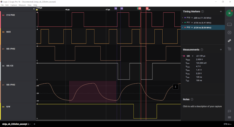
This raises the margin to 124 ns which apparently seems safer, but it starts to distort the signal a bit too much for my tastes. Besides, I cannot hear any differences, sound-wise. Taking into account that older 4520's cannot introduce too large a delay (I'll measure that when I get the parts I bought), I'd recommend sticking to 100 ohm.
NOTE: While I was making these tests, I was using a SwinSID Nano. Initially I could hear no difference, which got me pretty upset. Then I realized it kept working even if I disconnected the clock! So I looked for information and found out that the SwinSID does not care at all for the external clock, it generates its own internally. This means it is bound to working at the C64 frequency only and cannot be used on C16 SIDcards running at MUX/2. It would be nice if someone patched the SwinSID firmware for an alternative clock speed or if it just used the provided clock.
So the card is now working fine. I have already added the delay circuit to the PCB project (if one wants to use an old 4520, they can just use a 0 ohm resistor or bridge it). The last issue to solve is that the step-up voltage regulator is producing a bit too much noise. Can anyone report if the original SIDcard has a lot of hiss/whistling?
@TLC: Thanks for the info, that confirms that a very specific part is needed, and now it's documented for the future generations! Believe it or not, I absolutely s*ck at electronics when it comes to the analog aspects of signals or to how ICs are built and what characteristics they have. I used to think that CMOS would be faster, so Solder's note on his schematics "Normal CMOS" had me thinking that an HCT part would work. Oh well, that's the price for coming from the software world, I guess .
I agree that feeding the SID from a variable-speed bus is a huge hack that works by pure chance and thus I'd really recommend future SIDcard programmers to do what @gerliczer suggested initially: only access the SID during single-clock periods. That would definitely make things way more reliable.
Also thanks for your other suggestions, those are actually some of the modifications we have already made to the original design and which I have been talking about: we have removed the second stage of the amplifier and made sure that the first stage used the same values as the C64. These days you can easily do better amplification outboard. We have also added a volume control for the DigiFix and even a switch to completely bypass it. We have also recalculated the values for the step-up converter and came up with alternative ones for the 6581 SID, which is what I am actually using in my tests.
I'll wait for the old 4520's to arrive, test them and then make the project available for the public! Guess it will take a couple more weeks but we're close!
|
|
Posted By
gerliczer
on 2022-08-29
05:01:30
| Re: Solder's SIDcard Replica
I'm not aware of any SwinSID type device using the system clock. And I wouldn't bet on any SwinSID getting such patch ever. I tried to check what the situation is with FPGASID but seemingly that is not using the system clock either. But ArmSID is supposed to be using it.
|
|
Posted By
SukkoPera
on 2022-08-29
06:27:20
| Re: Solder's SIDcard Replica
I was using a SwinSID for the initial testing as I was afraid of destroying a precious SID, but well... SwinSIDs:
- Do not require the second 9/12V supply voltage
- Do not require external capacitors
- Can compensate for a missing 1k resistor to ground on the board
- And now I find out they do not even use the provided clock
... So I guess they weren't a particularly well-chosen testing device .
|
|
Posted By
Frenetic
on 2022-08-29
07:22:24
| Re: Solder's SIDcard Replica
@SukkoPera if it helps (and if you have/get access to a Teensy 4.1), I could send you a SIDKick-PCB (with the ICs populated) in about 2 weeks
|
|
Posted By
SukkoPera
on 2022-08-29
08:30:26
| Re: Solder's SIDcard Replica
@Frenetic: That would be a cool idea, provided that it is able to run at whatever external clock it gets. Of course I'd love to send a ReSeed (that's the name of my project) PCB in exchange if you want! I don't currently have a Teensy 4.1 but I can always buy one . Did you think of switching to a Raspberry Pico? Could it be done?
|
|
Posted By
Frenetic
on 2022-08-29
17:10:27
| Re: Solder's SIDcard Replica
well, it takes the external clock, tested in PAL and NTSC C64/C128. No idea what happens in other machines/clock speeds - find it out! (can you write me a mail, it's in the github repos)
Pico: no way SIDKick uses reSID 1.0 (0.16 optional), and I had to optimize around some precalculations and table sizes to get it working on a Teensy with 816MHz. I didn't want to develop the n-th SID emulation with compromises with regard to quality (and in the end fix incompatibilities for years), given that reSID is really superp.
|
|
Posted By
SukkoPera
on 2023-02-06
03:39:38
| Re: Solder's SIDcard Replica
Well, it took some time but I was finally able to test the older 4520 chips and the card works perfectly with them!
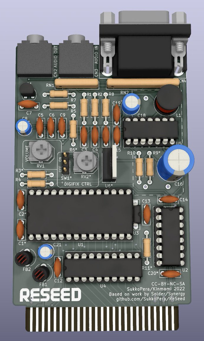
Thus, it was finally time to make the project public and release the board: the project page is available here with all the design files and docs. There is also a link to get the boards made by PCBWay, but I have a special offer for all people of this forum: if you want a couple of PCBs, you can get them for just the shipping costs, just write a PM to me!
Thanks to all those who helped and enjoy!
@Frenetic: Now it's also time for that email! :)
EDIT: I took scope measurements of the different 4520 chips:

You can clearly see how much faster (~90ns on the rising edge, even ~130ns on the falling edge! Vih=2V, Vil = 0.8V) the 74HCT4520E is (yellow) wrt the older SGS-Thomson CD4520B (white). Blue is SID /CS and pink is C16 PHI2.
EDIT 14/11: I spent the last few days perfecting the card. There was some annoying hissing and whistling in the background which I managed to eliminate after maaaany attempts by replacing R8 with a 3.3 or 4.7 ohm resistor (was originally 1 ohm). This solves 90% of the problem with 8580 SIDs, while some hiss still persists with 6581s, which can be totally eliminated by using 100 uH for L1 and 130 pF (yes, an uncommon value but worth it!) 100pF for C15. These values also help with 8580s but the effect is far less noticeable.
These values will be the default in V2 of the card which we should be testing soon and which also has a few more modifications to improve the quality of the audio output (and more!). This is also why I still haven't shipped any of the cards I promised, as I plan to send V2 cards. Hope the extra wait won't be a problem!
I have also prepared a comparative audio test so that you can judge the output quality for yourself: it opens in Audacity, use the Solo buttons and enable one track at a time:
- Top track is from a CAE card with an 8580 SID.
- Middle track is from a ReSeed V1 with R8=4.7ohm with the very same SID as the CAE track.
- Bottom track is from a ReSeed V1 with R8=4.7ohm, L1=100uH and C15=130pF with a 6581 SID.
The tracks are synchronized, so you can switch while listening. Also try panning one on the left side and a different one on the right side for some nice effect :).
Enjoy!
EDIT 04/02/2023:
So! I've been building and testing V2 of the SIDcard. The focus for this version was on reducing the output noise. Following is a list of the changes:
* New component values for the step-up voltage regulator: The values of some components were fine-tuned (again) in order to place the switching frequency of the step-up voltage converter way out of the audio band. These new values can also be retrofitted on a V1 board and will improve things dramatically (See V1.1).
* Alternative voltage step-up module: Cheap step-up voltage boost modules can now be used instead of the TL497-based circuit. Such modules, which can be easily sourced from Chinese portals, are much more modern and use a higher switching frequency, resulting in (near-)zero switching-induced noise. Using them also speeds up the assembly process, as many components can be skipped.
* Linear Regulator: If you are really paranoid about switching-induced noise, you can use the above alternatives as a first-stage voltage regulator and then make a second stage through a linear regulator, which should "eat" any remaining noise and provide the SID with very stable power.
* Separate grounds: A separate audio ground plane was introduced and connected to the signal ground plane through a single ferrite bead, preventing noise from spreading from the latter to the former. A second ferrite bead was inserted on the incoming +5V power rail in order to make it cleaner.
* Alternative BJT footprint: An alternative footprint for the output amplifier transistor was added, allowing for the mounting of the 2SC1815 BJT used in the original C64 audio circuit.
* SID clock delay circuit: This allows use of CD74HCT4520B chips in place of the CD4520B.
* Clock divider reset: Makes sure the SID clock always has the correct phase upon startup/reset.
* Short-circuit protection: In the original Solder design, a short-circuit can happen on the joystick port if it is written to. Series resistors were added in order to avoid this situation.
It works really well. The very last thing I am testing is the paddle/mouse/analog joystick circuit. I have been playing a lot of Arkanoid +4 Analogue Edition (Nice music, BTW!) and I found this could be improved: Solder used 100 ohm resistors in series with 3.9nF caps in the circuit. Comparing these to the C64 circuit suggests that the resistor was introduced to approximate the internal resistance of the CD4066 switch that the C64 uses to switch between the two joystick ports, while the capacitor is larger than the 2.2nF used in the original circuit. I found that these values greatly reduce the usable range of the paddles, meaning that the maximum value is reached at 3/4 of the whole paddle rotation. Did anyone else notice this? I tested with 2.2nF and it looks like that allows using almost the full range of the paddle. That makes it mostly OK but I will try lowering the resistor as well. I have also noticed that the 6581 SID requires even lower caps (1.8nF), so I think I will remove those values from the silkscreen and make them depend on the SID model.
Another oddity is that I had left the 3 higher bits of the joystick register floating, as I didn't have the space to pull those high when I added the short-circuit protection resistors. This shouldn't be a problem, but with Luca's help we found out that Solder's Joystick-Testprogramm detects fire button presses by checking if the read value is > 15 rather than checking whether bit 4 is set, which means it detects spurious fire presses. I believe this is a bug in that software (and Luca has already provided me with a fixed version, thanks a lot!), but anyway I will also fix that before the final release, just in case other games have the same bug.
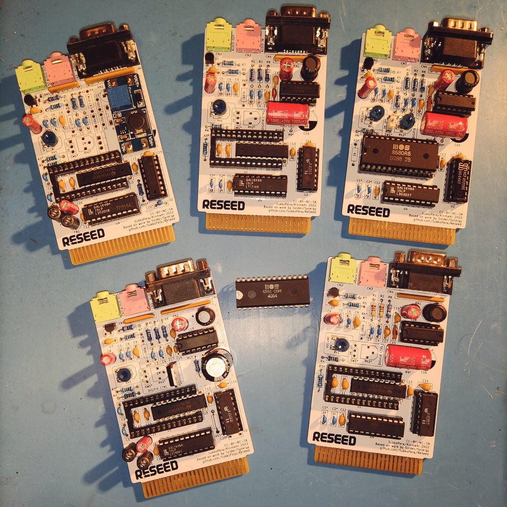
The two cards on the left are V2, the rest are V1.
I have also released V1.1, which is just V1 with the BOM updated with the changes I had already announced which dramatically reduce the output noise. Note it still has the 3.9nF cap in the paddle circuit though.
|
|
Posted By
Wayne
on 2023-02-04
12:08:55
| Re: Solder's SIDcard Replica
Hi There ! I would Very Much like to Buy one of these - Please Email me at wayne.womersley@gmail.com
Many Thanks for your help in advance :->
Wayne
|
|
Posted By
SukkoPera
on 2023-02-06
03:34:47
| Re: Solder's SIDcard Replica
@Wayne: I only rarely sell my boards, my main target is people who like DIY, but you might be lucky this time . I will write an email to you as soon as I'm ready.
In the weekend I made a lot of tests and I am now fully convinced that the capacitor values to be used in the paddle circuit are those recommended by Commodore, as they yield a fuller usable range of the potentiometers. The series resistor does not have a big impact but it's better kept.
I just need to update the project with these findings and then V2 will be released.
|
|
Posted By
Wayne
on 2023-02-06
13:48:40
| Re: Solder's SIDcard Replica
SukkoPera - Thank You, Thank You, Thank You, a Thousand Times Thank You, I am Incredibly Grateful to you for your immense Kindness ! :->
|
|
Posted By
Bionic
on 2023-02-26
18:52:21
| Re: Solder's SIDcard Replica
The CD4520 is an interesting story. I received (one of?) the first prototypes from Christian and when I tried it it sounded absolutely horrible. Turned out he had not tested it with real SID music yet. The issue was that the SID was originally clocked with the Phi2 signal, that is unforturtunately not constant in the Plus/4. He came up with the fix deriving the clock for the MUX signal using the CD4520. I also implemented the same fix, deadbugging a CD4520 I found somewhere onto the PCB. Things worked fine. He later told me that using anything else than the CD4520 failed.
The clock frequency is, of course, still different from the C64. The result was still significantly better than the contemporary "frequency-converters" that were used to play C64 music on the Plus/4 at that time. So I guess nobody cared.
Ten years later, I built a prototype based on a CPLD (data synchronization is more complex when the clocks are mismatched) and a 8701+XTAL from a C64 that fixed that issue. I did not follow up further, unfortunately. But there are other cards available in the meantime.
There is a lot of 80ies electronic design legacy in solders card (TL497, GAL, discrete audio amp). I wonder how an accessible design would look like today? Maybe using a MCU to implement all the glue logic, to avoid the need to source logic ICs?
|
|
Posted By
SukkoPera
on 2023-02-27
03:12:19
| Re: Solder's SIDcard Replica
This is an interesting insider detail about the development of the original SIDcard, thanks for sharing .
In ReSeed V2 we have pretty much revised and improved every single detail of the SIDcard. It's true that a lot of 80's electronics remains, but first of all I think it's sort of period-correct and then modern solutions are more expensive and not as easy to handle: GALs can be found easily and can be programmed with a TL866 programmer, while finding a small 5V-tolerant CPLD/FPGA is hard per se, and next to impossible with the ongoing component shortage. It would also need a dedicated tool for flashing, some bloated development environment, not to mention that I have very little experience in VHDL/Verilog programming (not that I had much with GALs when I started this project...).
In V2 we give the option of using a modern step-up DC-DC voltage converter, but to be honest the TL497 works very well now that we have recalculated all the component values and it can power both SID models. A more modern CD4520 can be used, as we have added a delay circuit that works just fine. This means something like a 74x74 could also be used with just a few changes. It's still a hack but it seems to work pretty solid.
The audio amp is the only thing we MIGHT still work on in the future, switching to some opamp. But again, it's only a handful of common components and works pretty well as-is, so I feel it can also stay that way .
Having a way to clock the SID at 1 MHz would be an interesting feature, but as you say, it's very hard to implement. Besides, I think most C16 SID music was made for the lower frequency, so it wouldn't sound good.
I still haven't released V2 because something has upset me (not on this forum), but it's final and can be found in the devel branch if anyone wants to have a look... or contribute some improvements .
The current design is fully through-hole and can be self-built for less than 20€ in components (SID not included, of course). I think this is also a plus of keeping 80's .
|
|
Posted By
TLC
on 2023-02-27
11:25:35
| Re: Solder's SIDcard Replica
I might add, that BSZ' NAE / CAE is IMHO a proven example of the let's just use modern components league... it uses a CPLD to host all the auxiliary logic functions, uses a modern DC-DC converter, has a proper audio buffer stage, and does in fact support standard PAL C64 clock mode.
|
|
Posted By
SukkoPera
on 2023-08-12
17:21:38
| Re: Solder's SIDcard Replica
ReSeed V2 is finally released, sorry it took so long:
https://github.com/SukkoPera/ReSeed/releases/tag/v2
It works really well, but so does V1.1 .
As far as I'm concerned, the project is complete. I'm really happy of how it sounds and it's been a great learning experience: I learned about GALs, step-up converters, RC delay networks and probably something more. There would have been no Hannes expansion or LittleSixteen V4 or... (well, you'll soon hear about things that are currently in progress!) without ReSeed. And I can't believe it's only been about a year!
As usual, if anybody wants PCBs, I have a few I could sell for a small amount (these are immersion gold finished and come with a beveled edge connector).
|
|
Posted By
Wayne
on 2023-08-14
15:31:05
| Re: Solder's SIDcard Replica
THIS is a BRILLIANT Project ! I'd love to Buy One of these Ready Built if possible SukkoPera ? My Email is Further up in the Thread if anyone has one for me to Buy pretty pretty please ?
Thank You :->
|
|
Posted By
SukkoPera
on 2023-08-14
16:43:17
| Re: Solder's SIDcard Replica
I'd happily send you PCBs but you will have to buy the components and solder them yourself. I can't build anything at the moment unfortunately .
|
|
Posted By
Wayne
on 2023-08-14
17:52:36
| Re: Solder's SIDcard Replica
Thanks Sukkopera that is very kind of you but unfortunately I do not have a clue how to solder that is WAAAY out of my Knowledge and / or comfort zone ! Thank You for replying so quickly :-> Is anyone here reading this able to build me one - I will of course pay for Parts, Time Building it and Postage ( I am in the U.K. if we have any U.K. Readers on here ! ), Message me via Gmail and we can discuss a price before Work commences, just so I know how much I need to Pay you. Thank You. And apologies to all the Brainy ones.. I am a Noob with Technology, I can Switch the Machine On, Play Games and... Erm, that's it ! LOL We are not all Techy Geniuses like you - So Respect due to you all for what you are doing - I Bow before your Excellence.
|
|
Posted By
z9leca
on 2023-08-15
03:18:22
| Re: Solder's SIDcard Replica
Excellent project (among all your other excellent projects, SukkoPera - I need to get on the bandwagon and order some PCBs via PCBWay for your other C16/Plus4 stuff). Anyway - I would like to buy a PCB from you if there still are some available (and if you have some leftover for your other projects I'd probably want to buy for them too!).
Also - I'm not an expert at soldering but I
|
|
Posted By
z9leca
on 2023-08-15
03:38:55
| Re: Solder's SIDcard Replica
.. but I have done a bit of work so if you want, Wayne, I can make a board for you. Don't expect it to be the most beautiful thing you
|
|
Posted By
z9leca
on 2023-08-15
03:45:31
| Re: Solder's SIDcard Replica
... you've ever seen. You'd have to cover the component costs, postage and source a SID yourself, but I of course won't charge for the work. Let me know.
Best regards
Carl
(Sorry for the triple post - my posts gets cut in half for some reason)
|
|
Posted By
SukkoPera
on 2023-08-15
04:35:44
| Re: Solder's SIDcard Replica
I have some SIDcards and some of the other stuff, send me an email with what you need (quick, I can only ship next week) if you are interested.
To be honest, soldering most of my boards only takes a good iron and some good solder wire: easy DIY-ness is one of my explicit goals, that is why I always use through-hole components unless absolutely necessary (and never go below 0805 and SOP packages when doing SMT - unless absolutely necessary, lol), I try to stick to a small subset of components and I use common values as much as possible. Besides, since my boards can be ordered for cheeeeap (most are $ 0.50 each from PCBWay + shipping & customs unfortunately) and in batches of 10, they are the ideal starter job: if you mess up, just throw it away and start a new one .
On a side note, some Germans are organizing a collective order of ReSeed boards + components, maybe it can be useful for @Wayne or anyone (feel free to buy there, price is OK), check it out here.
|
|
Posted By
z9leca
on 2023-08-15
04:59:15
| Re: Solder's SIDcard Replica
I'll gladly send you an email, but I don't seem to find your email address?
|
|
Posted By
SukkoPera
on 2023-08-15
05:04:51
| Re: Solder's SIDcard Replica
Nickname at gmail would work .
|
|
Posted By
Wayne
on 2023-08-15
15:32:27
| Re: Solder's SIDcard Replica
@z9leca - I will take you up on your offer - My Gmail is wayne.womersley if we can continue the conversation there please ? :-> @Sukkopera - As Always Thank You again for your Assistance - what you are doing for the Plus 4 SScene is nothing short of INCREDIBLE :->
Thank You !
|
|
| |
Copyright © Plus/4 World Team, 2001-2025. Support Plus/4 World on Patreon |