Posted By

TLC
on 2023-07-10
06:52:45
|  Re: Luma / Chroma crosstalk fix Re: Luma / Chroma crosstalk fix
I thought I could make use of some gadgets that I had collected together (or, built) in the past 10-15 years  . That was slightly motivated by the fact that I had tried taking photos of the CRT monitor again, but they looked, well... as usual. So, the screenshots below were produced without using a CRT monitor. It was rather, like (connection types in brackets): Plus/4 --> (S-Video) --> Analog video decoder box --> (analog RGB over SCART) --> cheap Chinese analog video to HDMI converter box --> (HDMI) --> yet another cheap Chinese PC USB HDMI video capture gadget --> (USB) --> PC . Huh... . That was slightly motivated by the fact that I had tried taking photos of the CRT monitor again, but they looked, well... as usual. So, the screenshots below were produced without using a CRT monitor. It was rather, like (connection types in brackets): Plus/4 --> (S-Video) --> Analog video decoder box --> (analog RGB over SCART) --> cheap Chinese analog video to HDMI converter box --> (HDMI) --> yet another cheap Chinese PC USB HDMI video capture gadget --> (USB) --> PC . Huh...
Anyway, I think it was worth the effort.
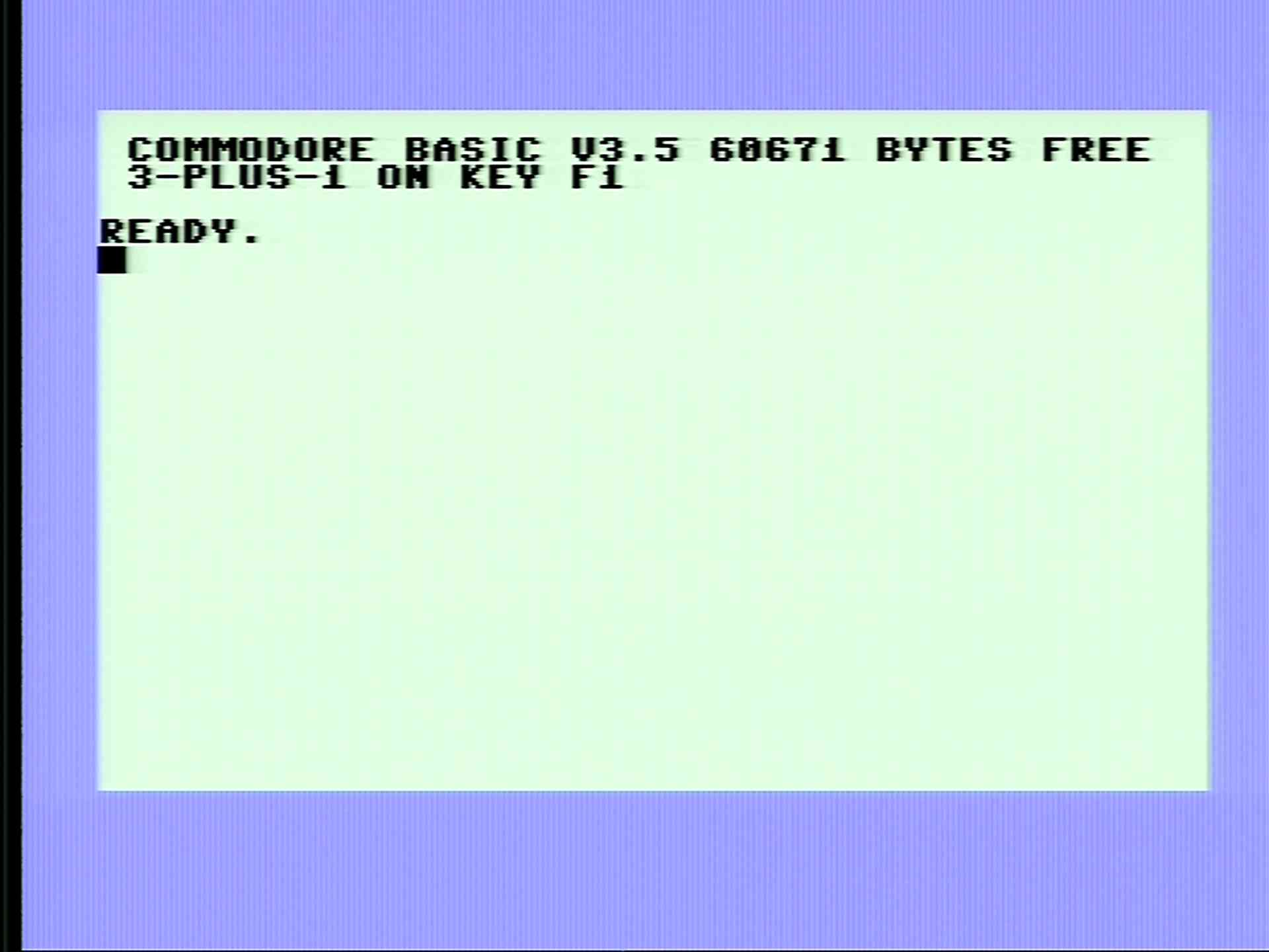
So first, this is what we're talking about (finally) WRT the stock machines:
Stock Plus/4's screen over S-Video:
The same screen after the fix:
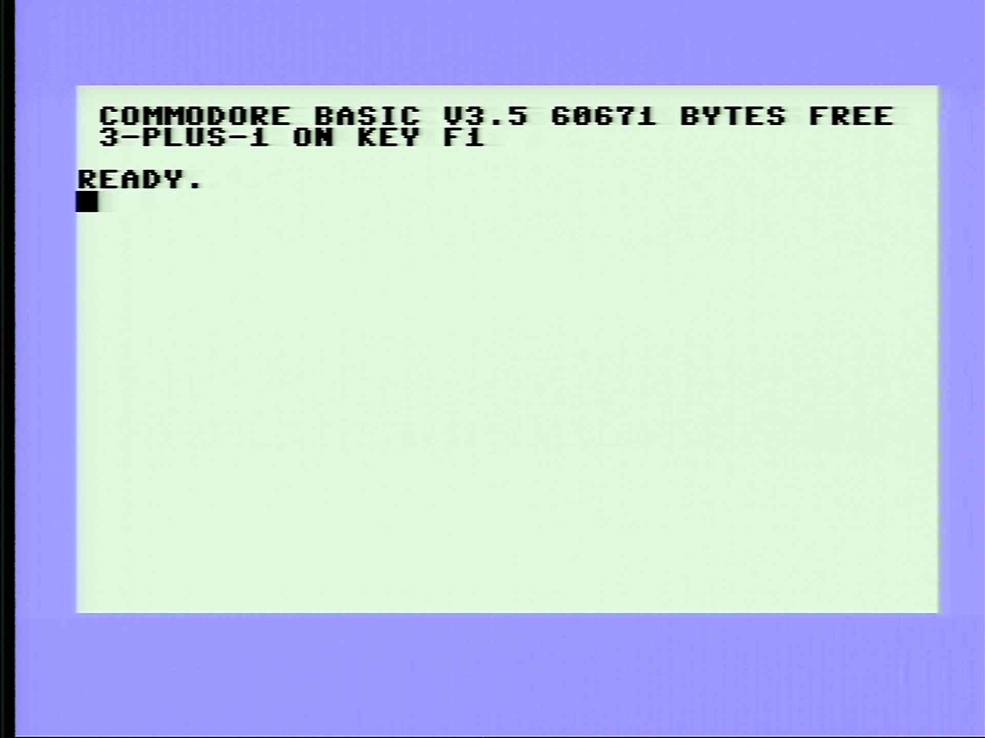
Note: the crosstalk would look a lot worse on the edges of multiple coloured fields in practice.
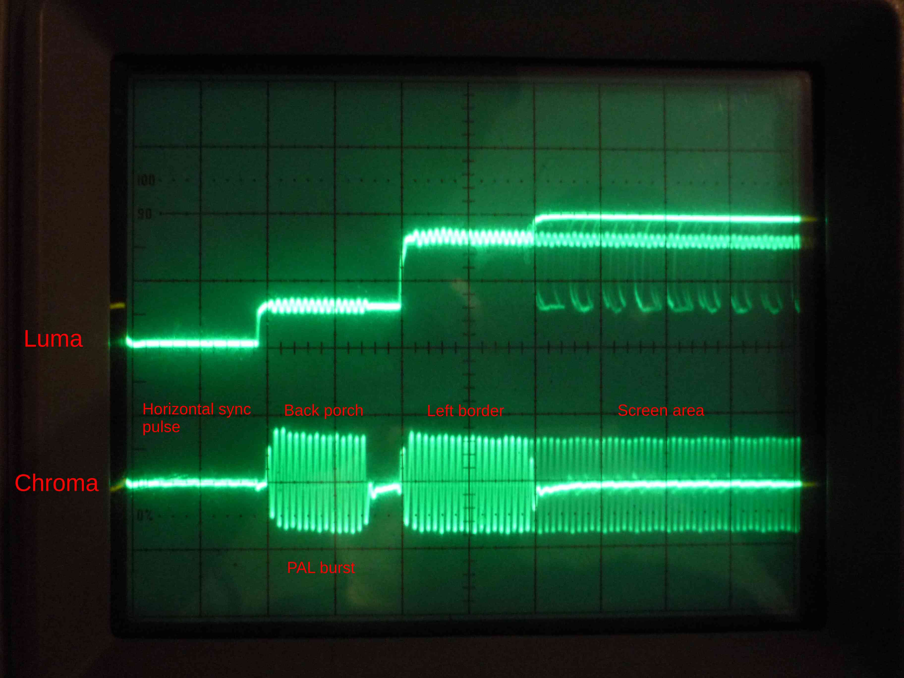
Luma and Chroma signals on an analog oscilloscope. The trigger was set to the beginning of the lines. The setup is a little bit confusing, as there's no way on this old, analog oscilloscope to trigger to one particular TV line, so, in fact multiple TV lines are superimposed to the same picture. This looks particularly confusing for the screen area, where upper and lower vertical borders, white background, and character bits and pieces are drawn to the same place.
The pictures below show the horizontal blank, the backporch, the left border, and the first few character places of the screen area.
Vertical scale is 0.5V, horizontal scale is 2 single clock cycles per division.
Stock machine:
Fixed:
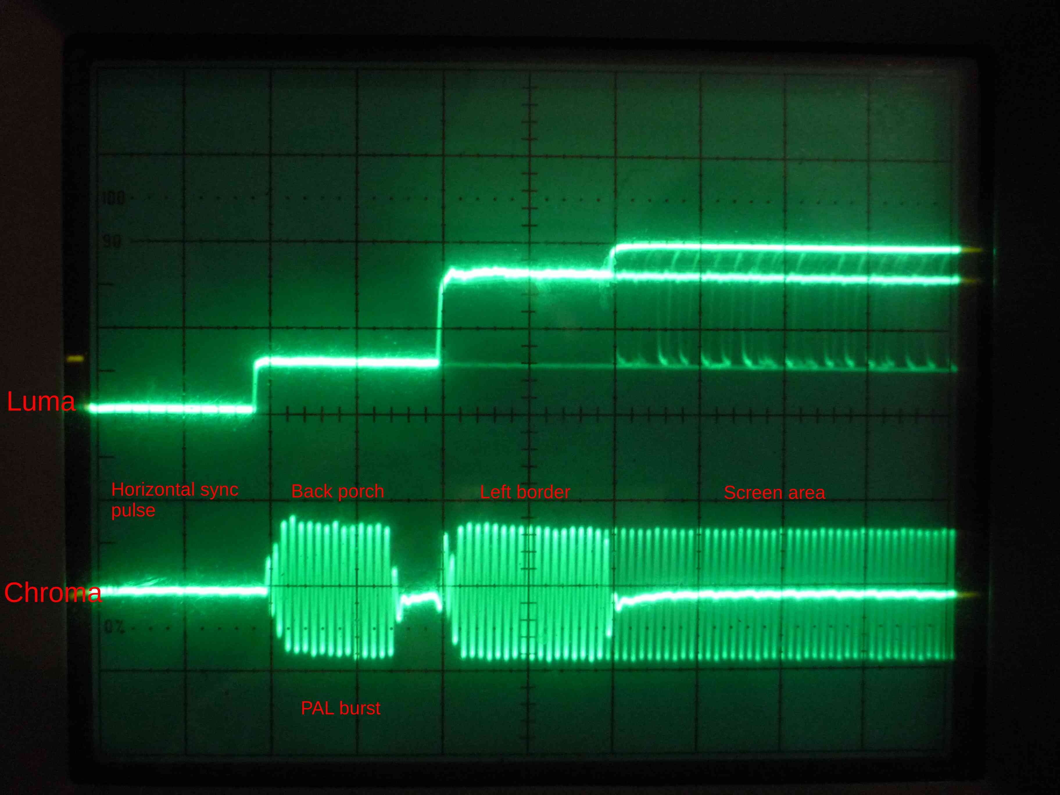
Note the differences. On the stock machine's Luma, there's a noticeable crosstalk everytime the Chroma signal is active. After the fix, Luma is bearably flat at any places (it's not perfectly flat, there's still a bit of noise from the internal signals of the machine, but there's at least no apparent chroma crosstalk anymore.)
And finally, one particular way to fix this.
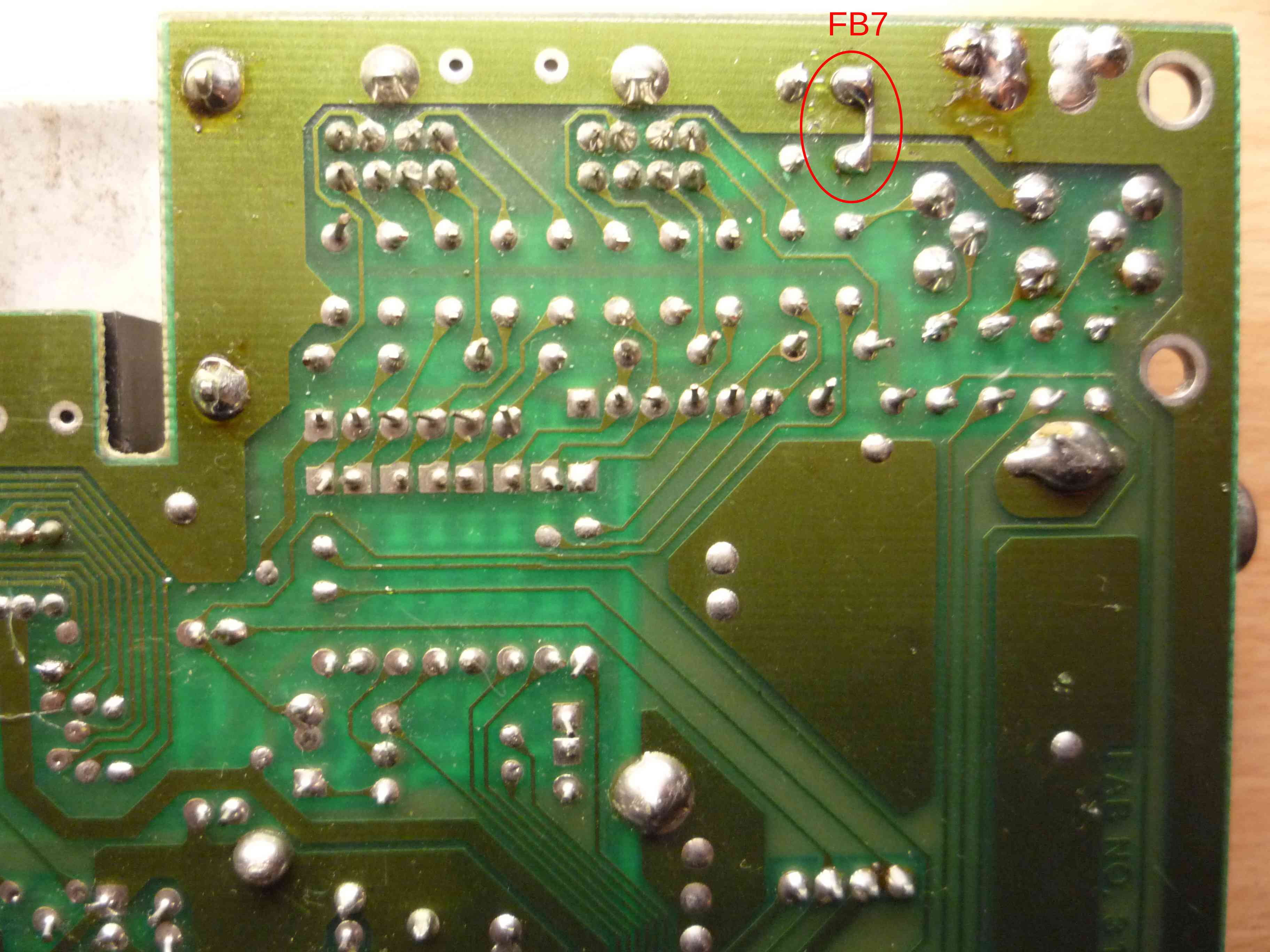
This is a slightly different PCB than what I've shown before (this is an earlier, Assy. 310163 type, my "work horse" Plus/4's motherboard).
Stock looks like this:
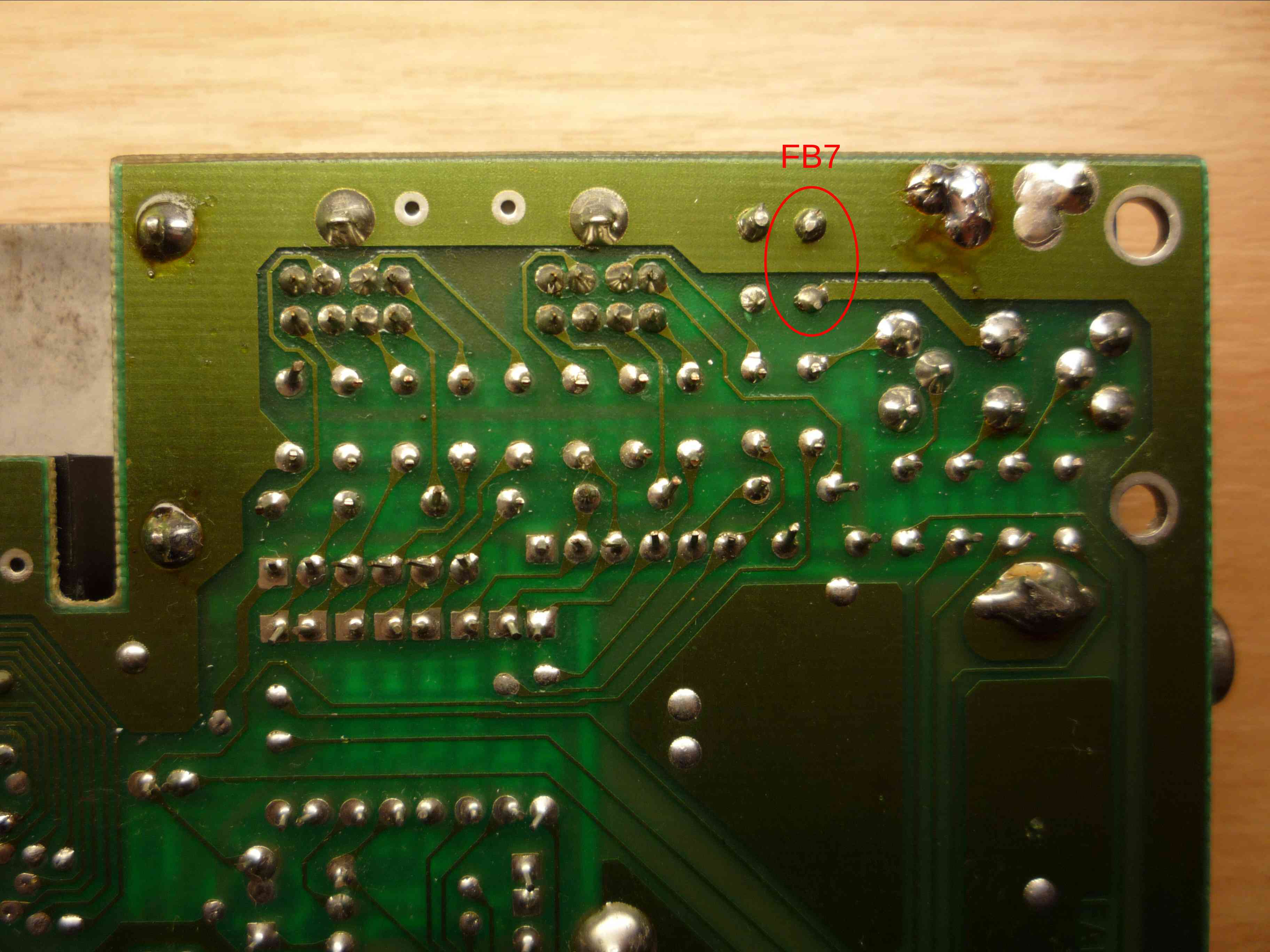
and then there's a small piece of wire soldered to FB7's pins, effectively bypassing it.
I think that's all about it.
One final note: the situation would be similar WRT an NTSC or PAL-N machine. (Pattern looks a bit different, but the overall look is similar.)
|