| Posted By

TLC
on 2023-07-01
17:44:48
|  Luma / Chroma crosstalk fix Luma / Chroma crosstalk fix
I'd open a new topic for this fix, or hack, whatever, as promised a couple of weeks ago.
Short summary: on all 264 series machines, there is a noticeable crosstalk distortion between the AV socket's output signals, which is apparently due to a design flaw that mandated using a ferrite bead filter in-series with the AV socket's common ground signal.
(No other Commodore 8-bit machines have this ferrite bead filter on the AV GND.)
The problem mostly affects the separate luma/chroma picture (--> chroma crosstalk on luma), and also does affect the sound output to some less extent.
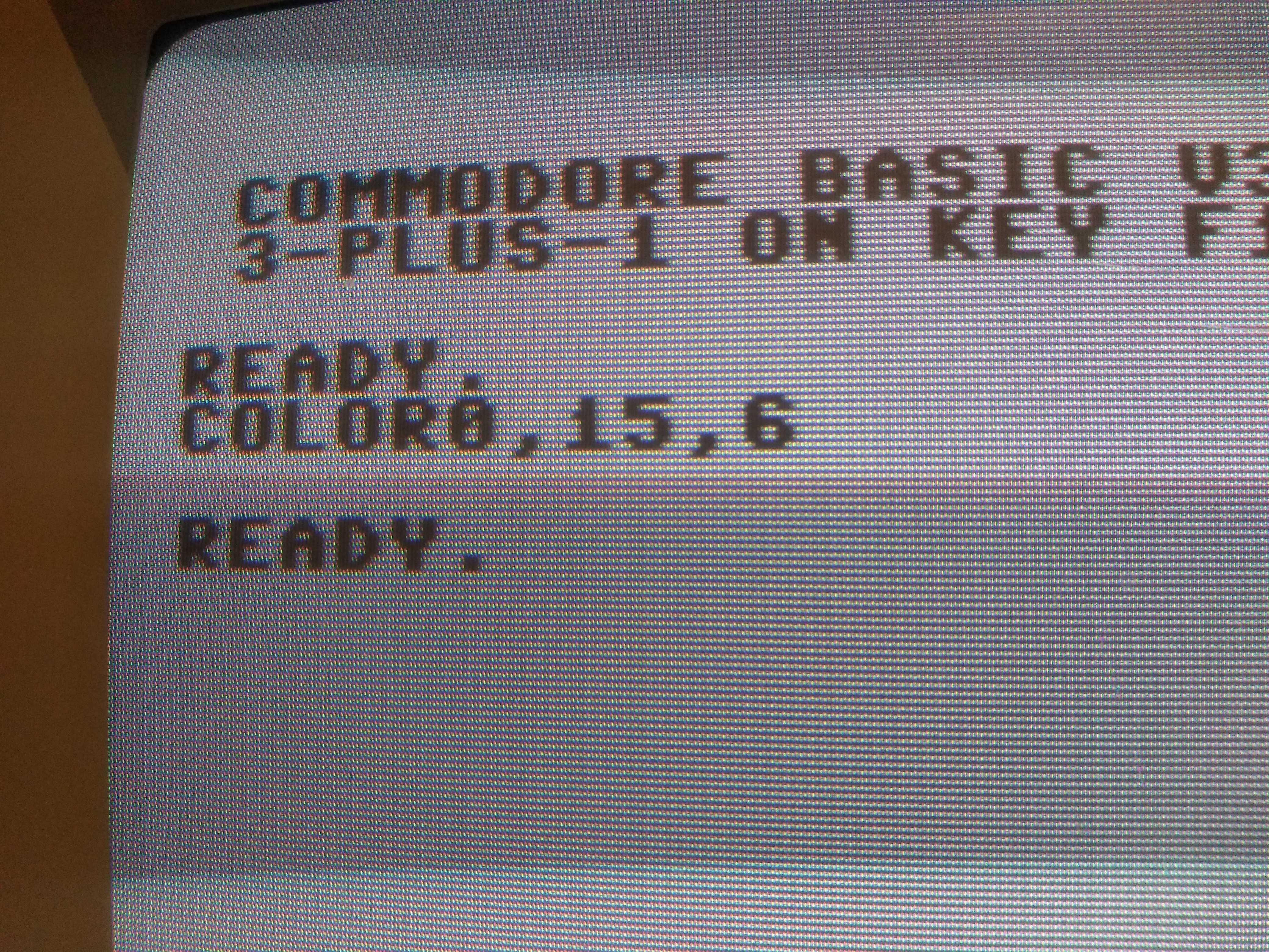
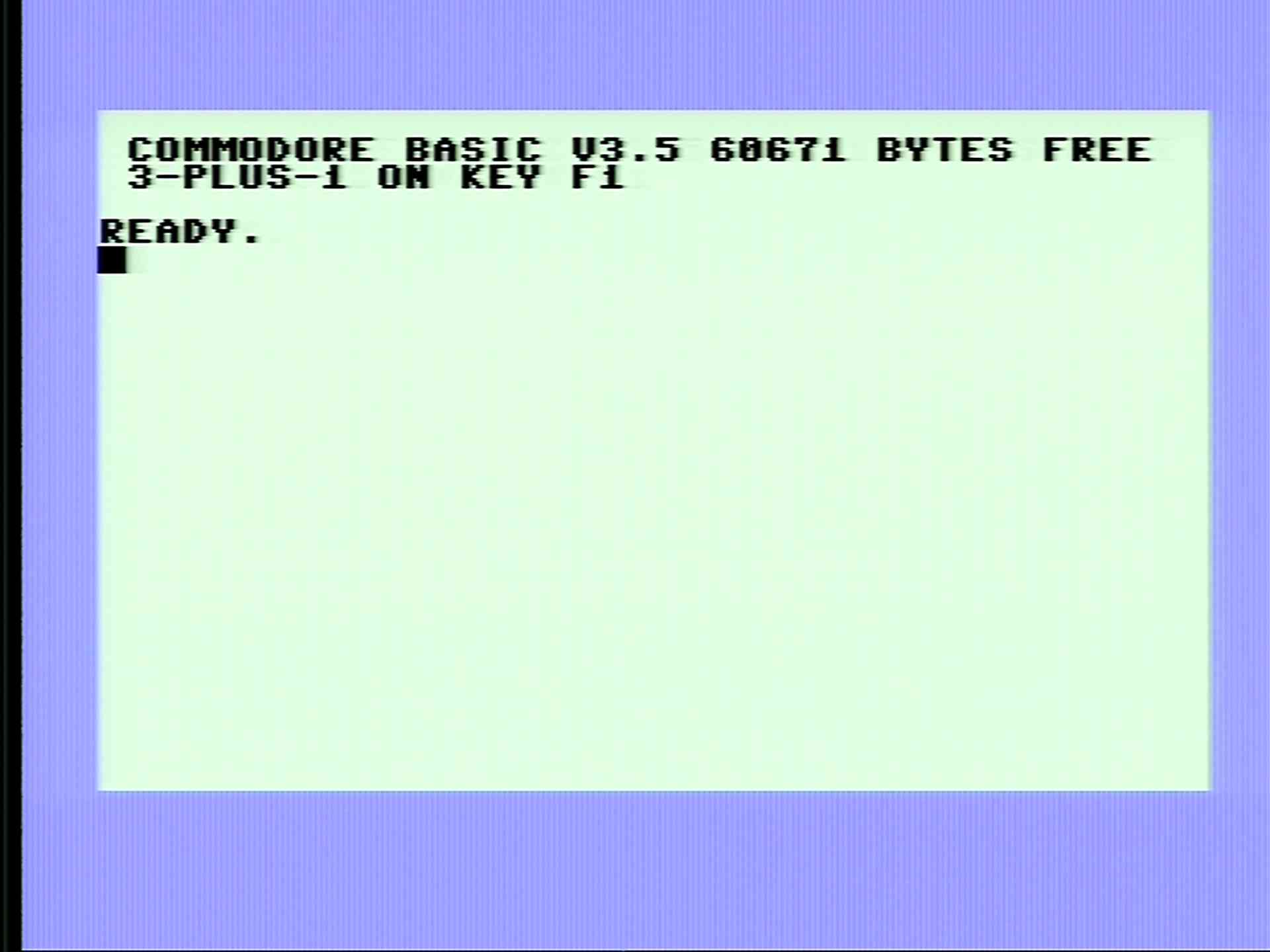
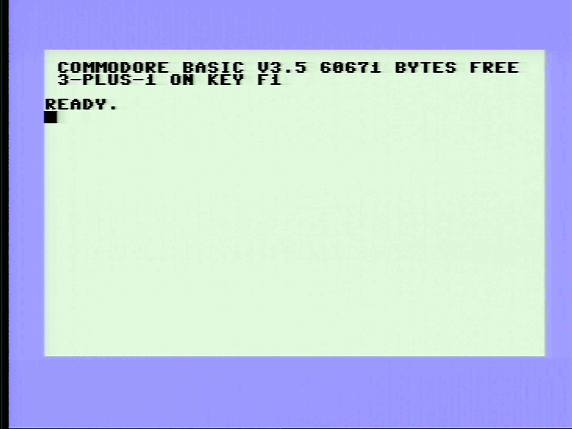
To illustrate the problem, let's see below how the luma image of the stock machine's "standard light blue" screen actually looks on a 1084S monitor. (This was captured using the separate luma/chroma input with luma disconnected, and the monitor set to separate luma/chroma mode).
Note the colour setup (i.e. the basic color 0,15,6 command used; together with the border colour set by power-on reset, that means uniform standard light blue over the whole screen).
The background is supposed to be completely flat, but it isn't. There's an overall grainy outlook, due to chroma signal crosstalk to luma.
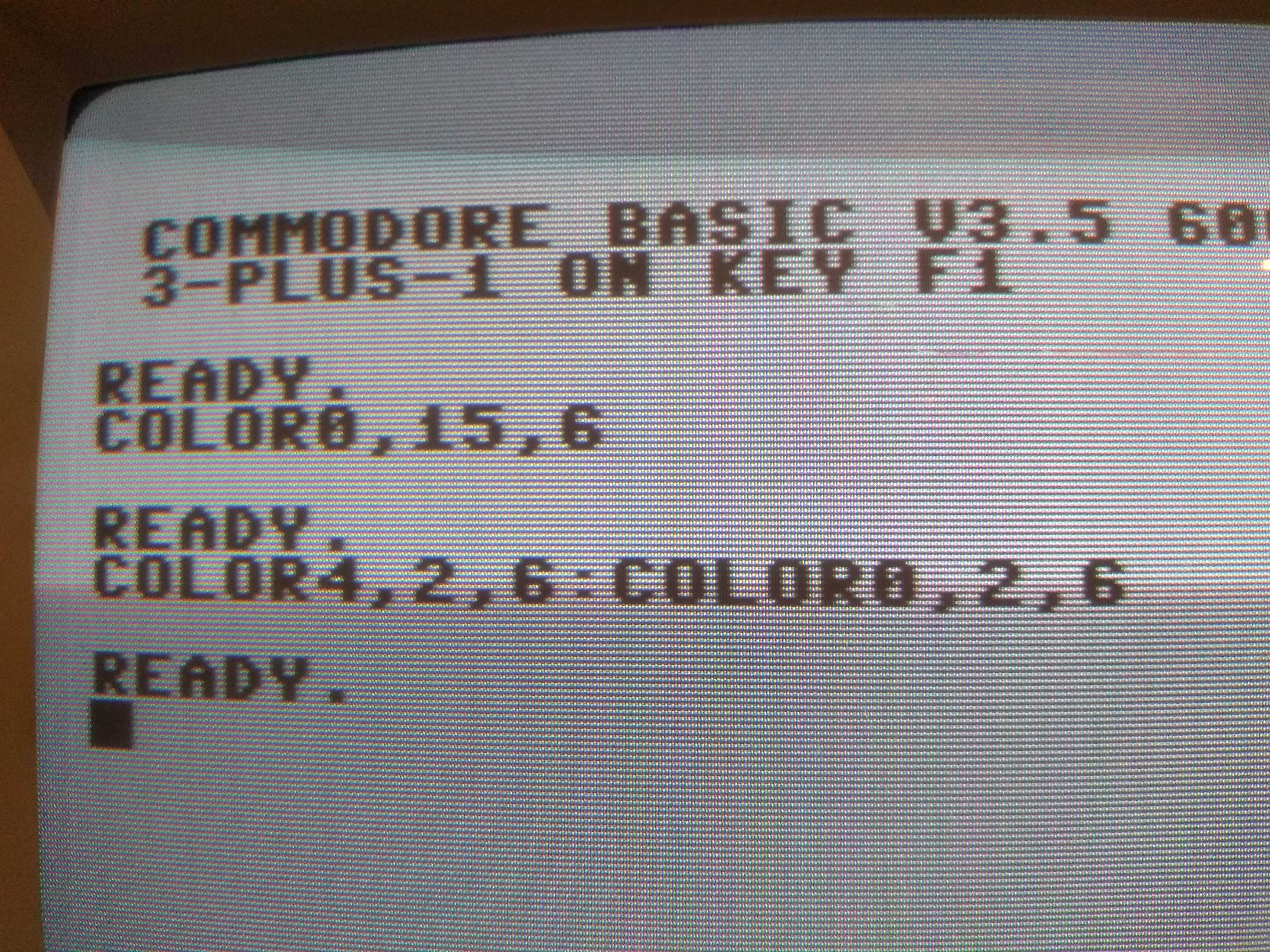
For a comparison, the colour can just be temporarily switched off, and one can see what happens. But, how? The answer is, that gray has no colour. Literally that means that chroma is switched off by the TED, dead, flat 0V, you name it, for grays, black, and white. If chroma is cut off, there's no way for it to induce crosstalk huh?
See the image below (note the basic colour setup commands again- only the colour code has been changed WRT to the previous test but no brightness levels). Now this image is flat*. That's actually how (i.e. how flat) any coloured images are supposed to display, was there no chroma crosstalk.
*The colour picture tube adds some level of graininess, which is apparent when captured with macro. This actually looks much better "in real life", and the image indeed looks completely flat smooth on monochrome picture tubes.
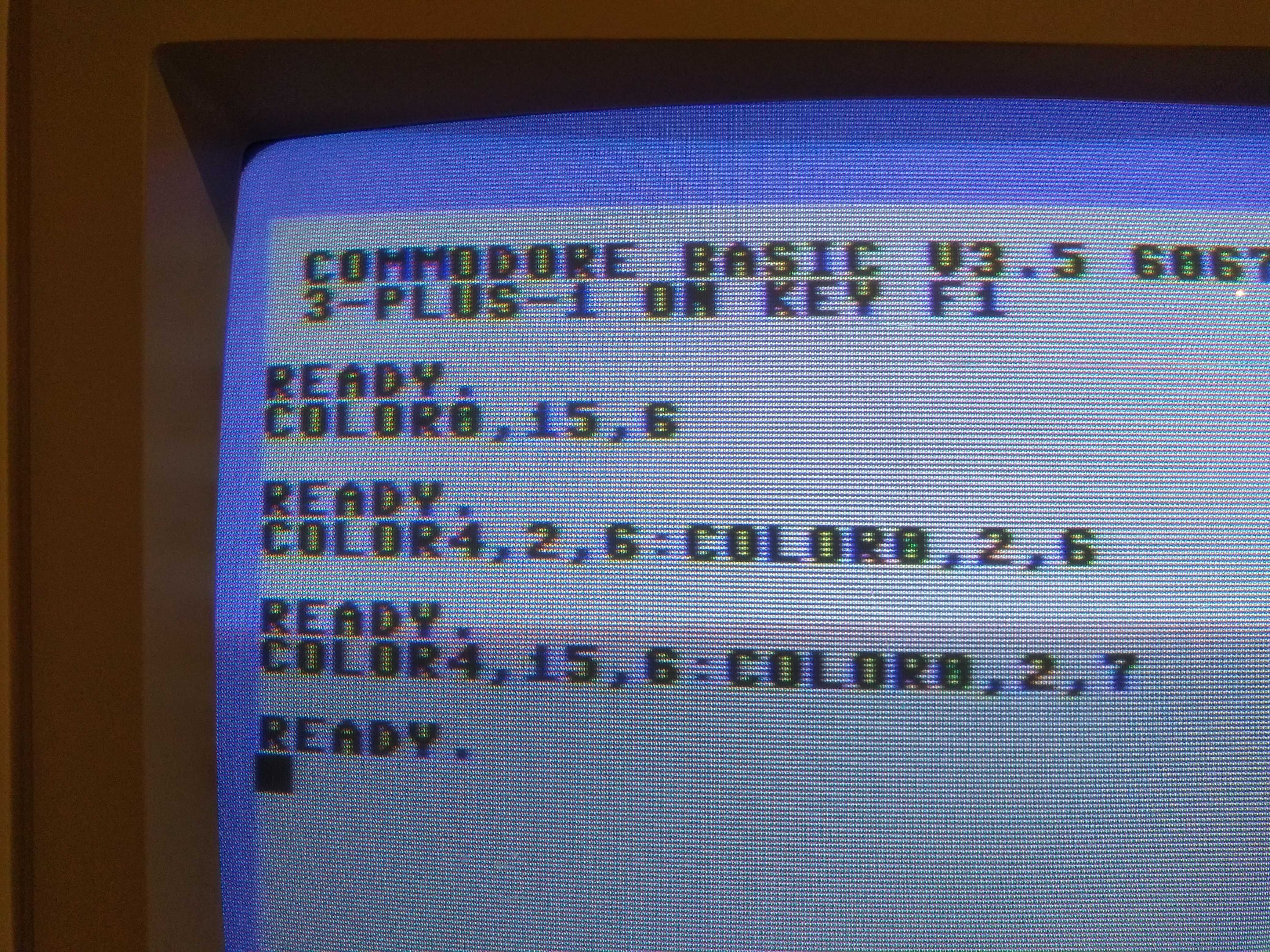
Just for curiosity, here's a picture about yet another test. I set the monitor to composite, and had it decode the chroma-crosstalk-ridden-luma signal as composite video. As one can see, the overlaid chroma content by crosstalk is so strong that the 1084S actually recognizes and displays this signal as valid colour composite signal. There are colour outline distortions here and there of course (partly due to the fact that luma was not bandwidth limited here as would be required for composite), but one thing is sure, chroma leak-in is strong enough for the decoder to recognize the content as valid colour.
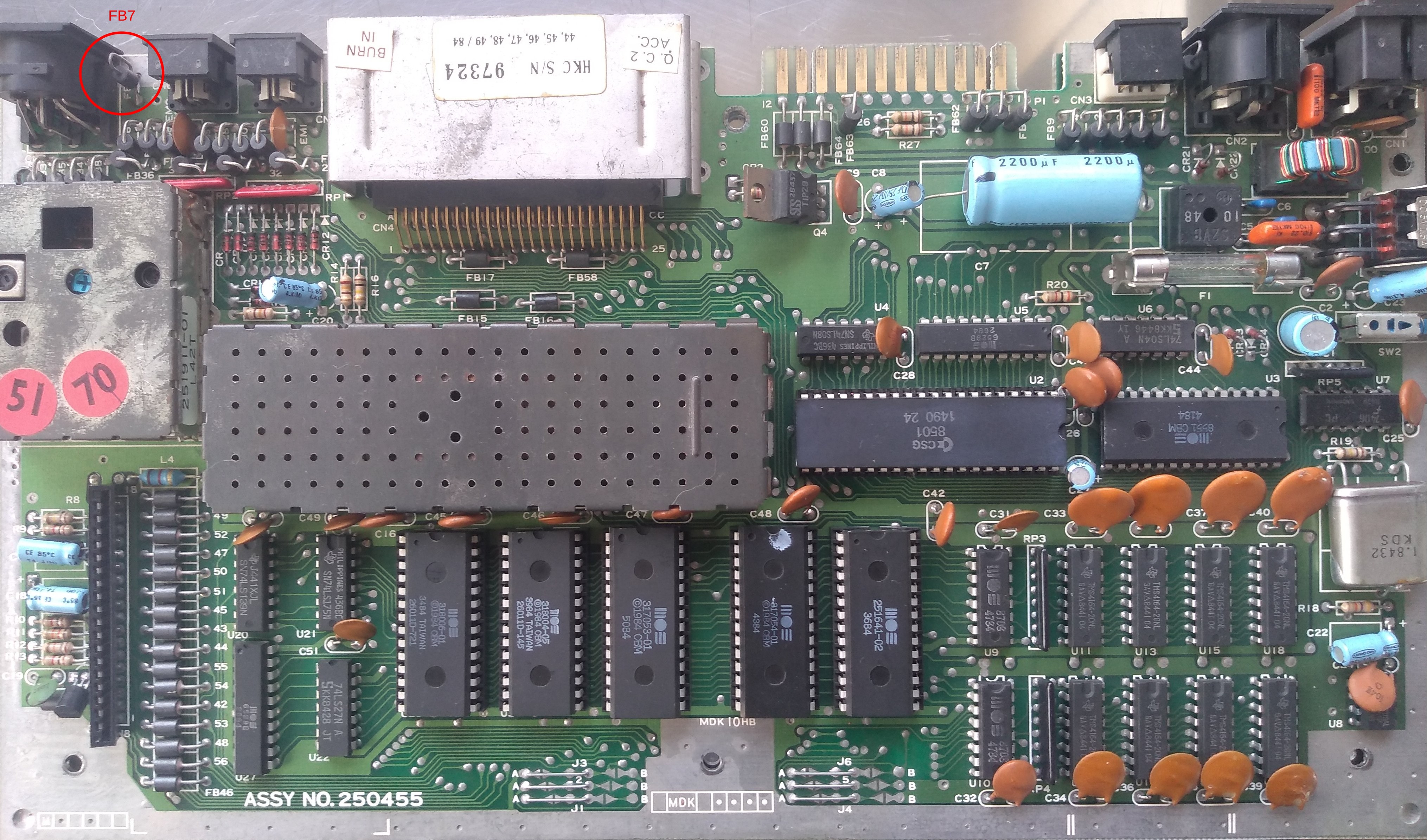
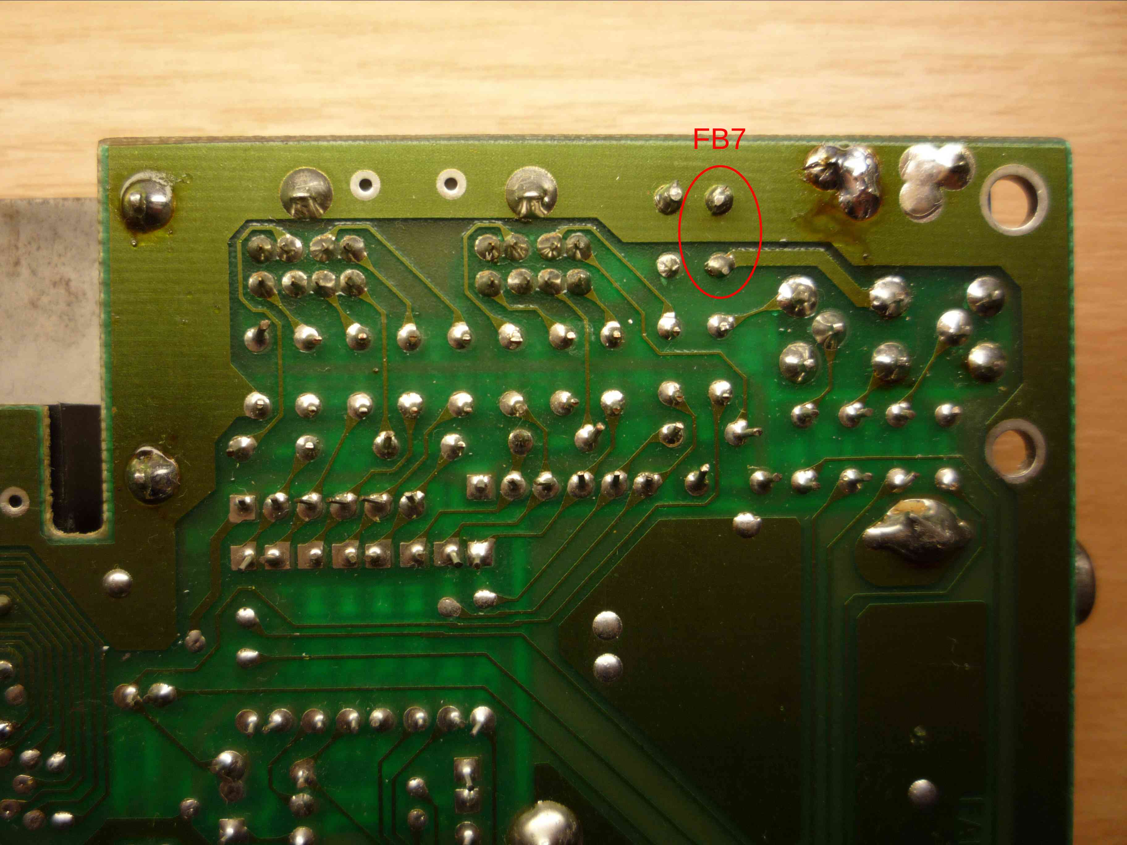
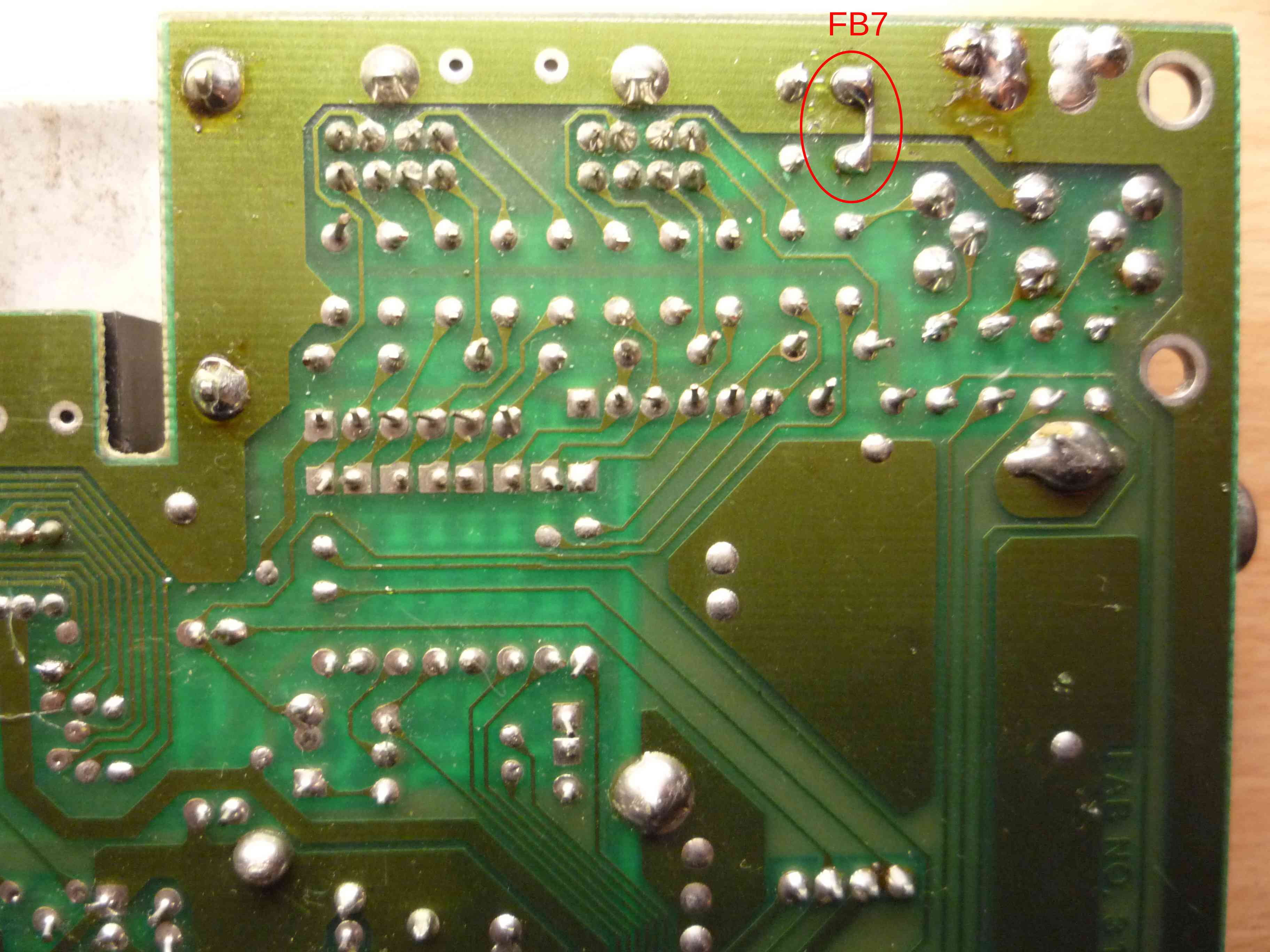
The problem's single culprit is FB7 in the Plus/4, and FB13 in the C16 and C116. It can be remedied by removing the FB and replacing it by a piece of wire, by simply shorting the FB's pins together by a piece of solder, by bypassing the FB altogether (connecting the AV socket's GND pin to the GND plane by a piece of wire), etc. This is a very simple hack.
Here's how this practically looks like in the Plus/4. (FB7 marked).
Note: this is a later, Assy No. 250455 board. FB7 is located in the same position on earlier 310163 boards.
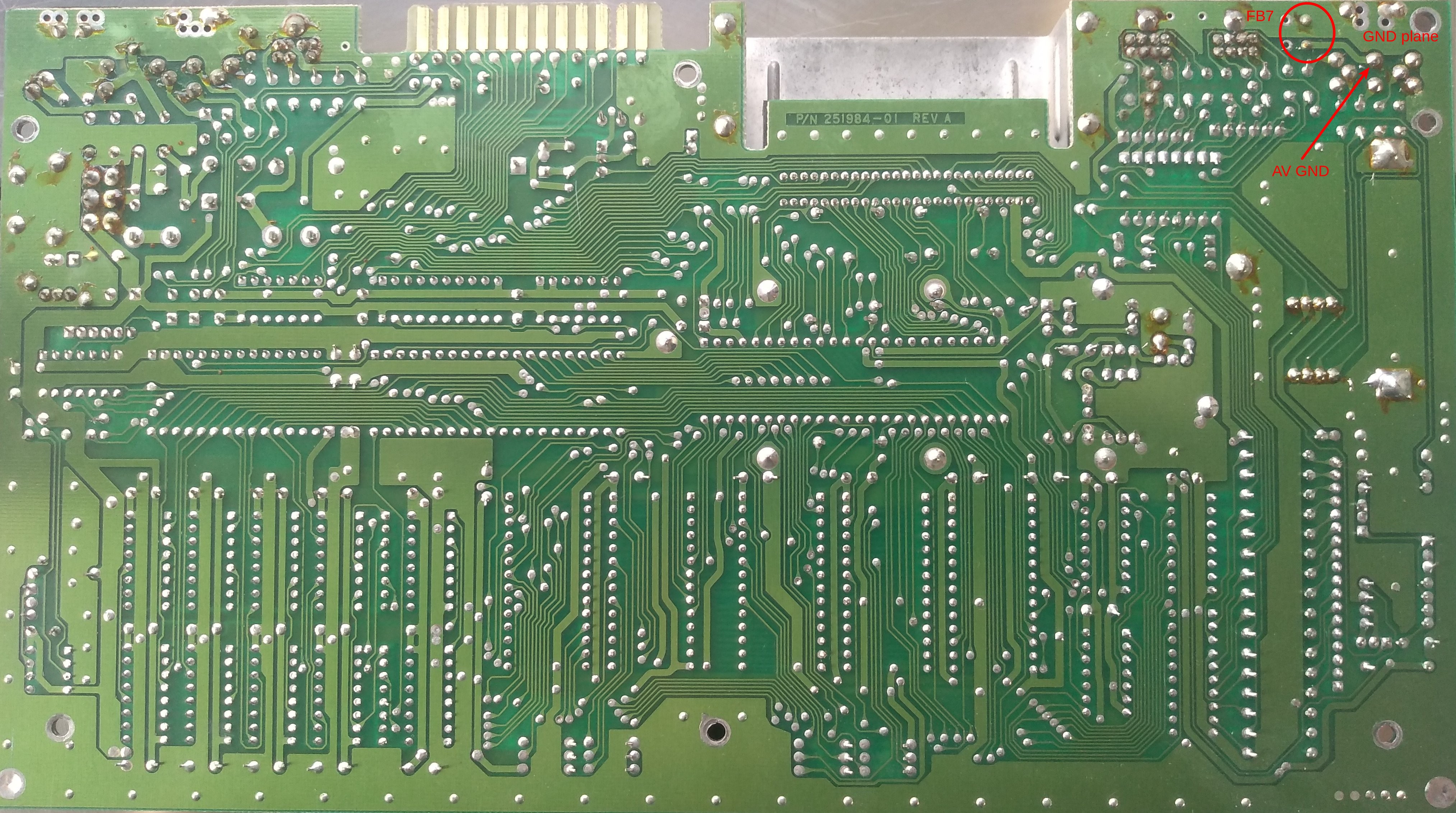
Solder side (FB7, AV GND point, GND plane marked):
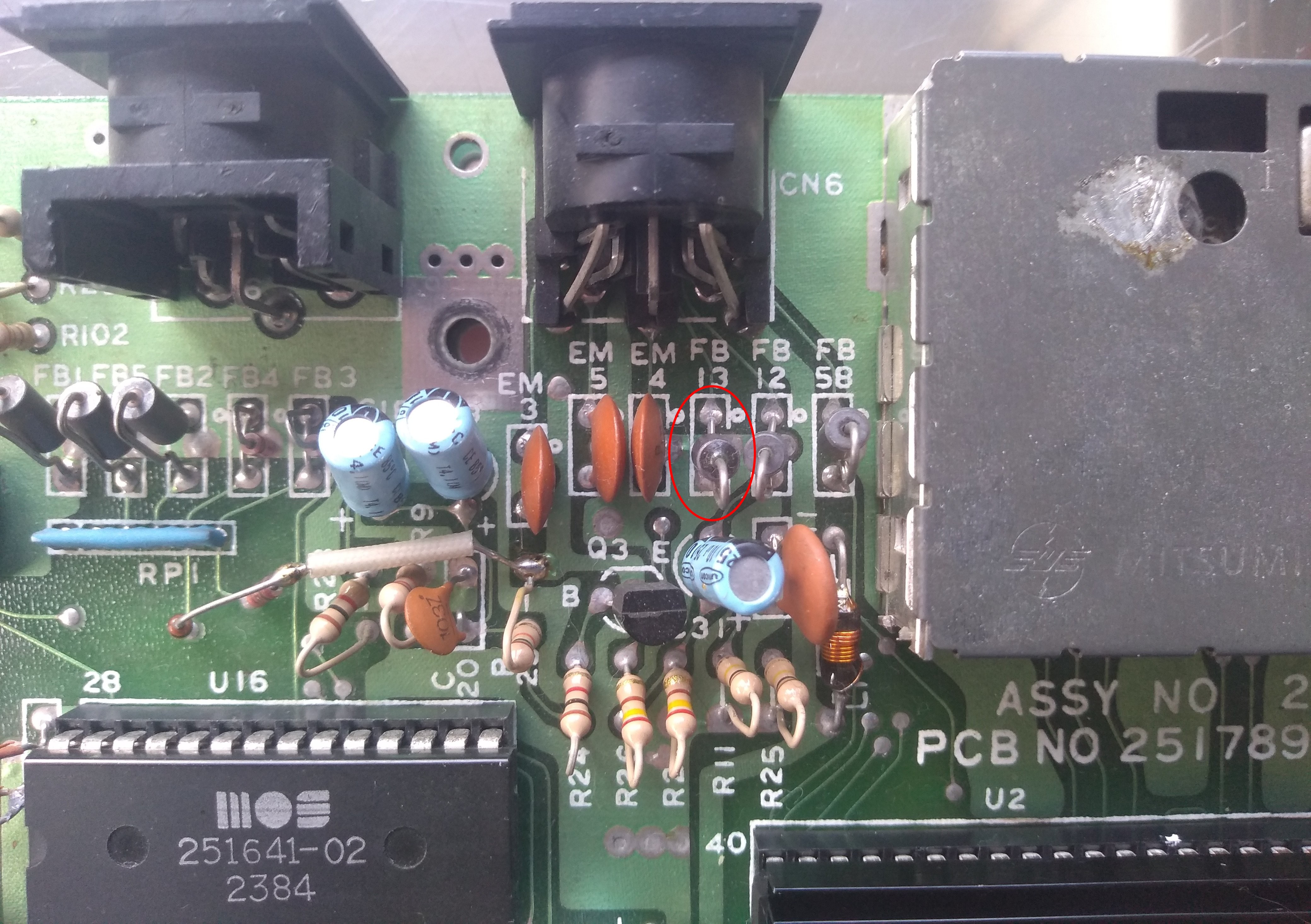
For reference, here are two pictures taken from the same thing in the C16. (No C116 images, sorry.) FB13 marked.
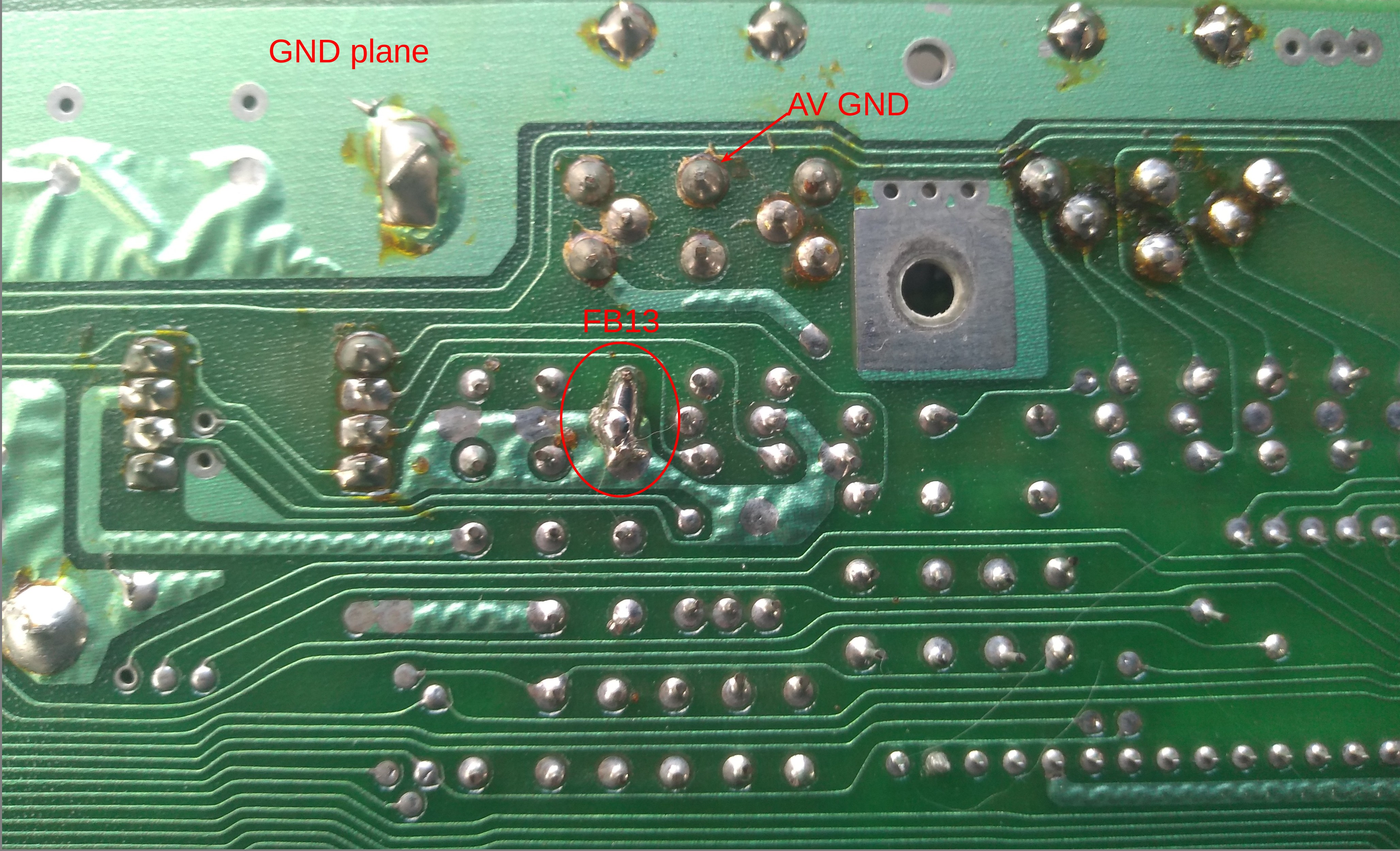
Solder side. As one could note, this C16 motherboard had already been fixed before, by applying a small bit of solder to the pins of FB13 (one particular way to fix, maybe the simplest one here).
I might be adding a few photos of how the contaminated luma signal actually looks like on oscilloscope, vs. one that's been fixed. Later.
|
|
Posted By
MIK
on 2023-07-01
18:12:07
 | Re: Luma / Chroma crosstalk fix
Interesting.
From what you have said, it's just a case of cutting the FB7 bead out of a Plus/4 and then join the remains back together, (the 2 pins left behind) and that's it??
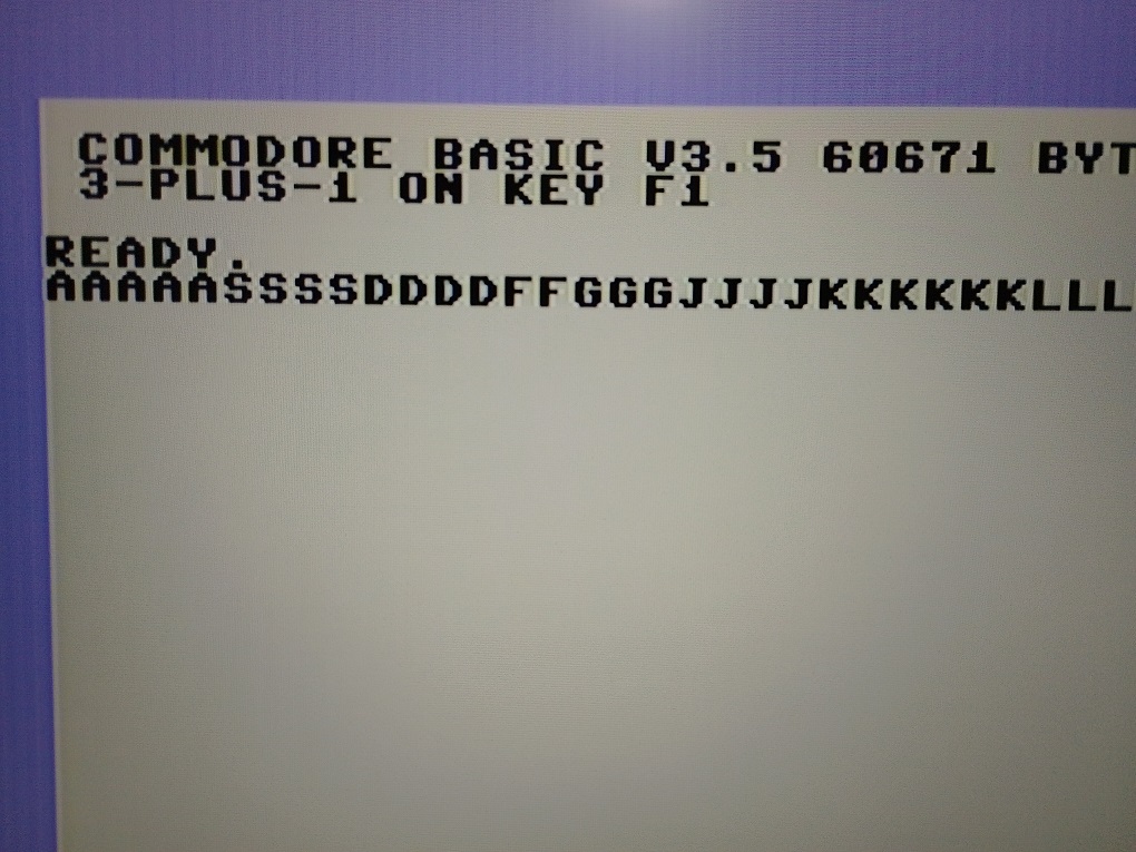
Will this hack remove the yellow that is bleeding out of the Basic text that we see on your full colour Plus/4 screen?
|
|
Posted By
TLC
on 2023-07-03
16:34:53
| Re: Luma / Chroma crosstalk fix
@MIK it doesn't even need to be cut, I mean it's enough to short the terminals. (The easiest way is probably to solder a small piece of wire to the terminals, on the PCB's solder side. Will make photos, I'll have to get around to do them. At least I have prepared the machine for that, but I have to find time for arraning the test and the photos).
Re. colour bleeding: the photo above is about a "nonstandard" setup. With that I merely intended to show, that chroma crosstalk to luma is quite pronounced here. On a stock Plus/4, chroma content (signal level) on luma is ultimately so large by the crosstalk, that, when this signal is fed to a composite display, the ident circuit happily identifies the colour subcarrier there, and the colours are shown. The apparent colour bleeding is specific to this setup, it's a result of displaying unfiltered luma content on a composite display. (Composite requires luma to be bandwidth limited, but here, it isn't). This bleeding doesn't appear on standard setups.
|
|
Posted By
MIK
on 2023-07-03
19:42:04
| Re: Luma / Chroma crosstalk fix
Cool, thanks. No need to rush, look forward to seeing some pictures. 
|
|
Posted By
TLC
on 2023-07-10
06:52:45
| Re: Luma / Chroma crosstalk fix
I thought I could make use of some gadgets that I had collected together (or, built) in the past 10-15 years . That was slightly motivated by the fact that I had tried taking photos of the CRT monitor again, but they looked, well... as usual. So, the screenshots below were produced without using a CRT monitor. It was rather, like (connection types in brackets): Plus/4 --> (S-Video) --> Analog video decoder box --> (analog RGB over SCART) --> cheap Chinese analog video to HDMI converter box --> (HDMI) --> yet another cheap Chinese PC USB HDMI video capture gadget --> (USB) --> PC . Huh...
Anyway, I think it was worth the effort.
So first, this is what we're talking about (finally) WRT the stock machines:
Stock Plus/4's screen over S-Video:
The same screen after the fix:
Note: the crosstalk would look a lot worse on the edges of multiple coloured fields in practice.
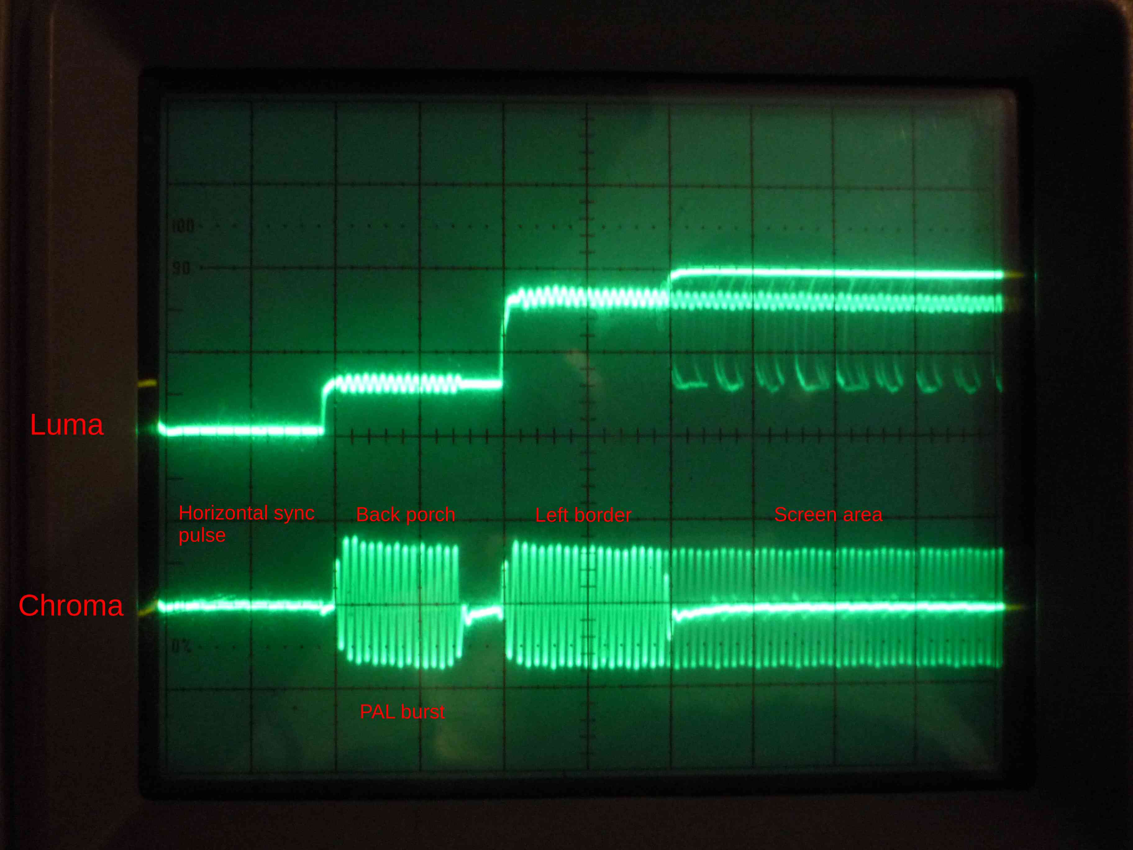
Luma and Chroma signals on an analog oscilloscope. The trigger was set to the beginning of the lines. The setup is a little bit confusing, as there's no way on this old, analog oscilloscope to trigger to one particular TV line, so, in fact multiple TV lines are superimposed to the same picture. This looks particularly confusing for the screen area, where upper and lower vertical borders, white background, and character bits and pieces are drawn to the same place.
The pictures below show the horizontal blank, the backporch, the left border, and the first few character places of the screen area.
Vertical scale is 0.5V, horizontal scale is 2 single clock cycles per division.
Stock machine:
Fixed:
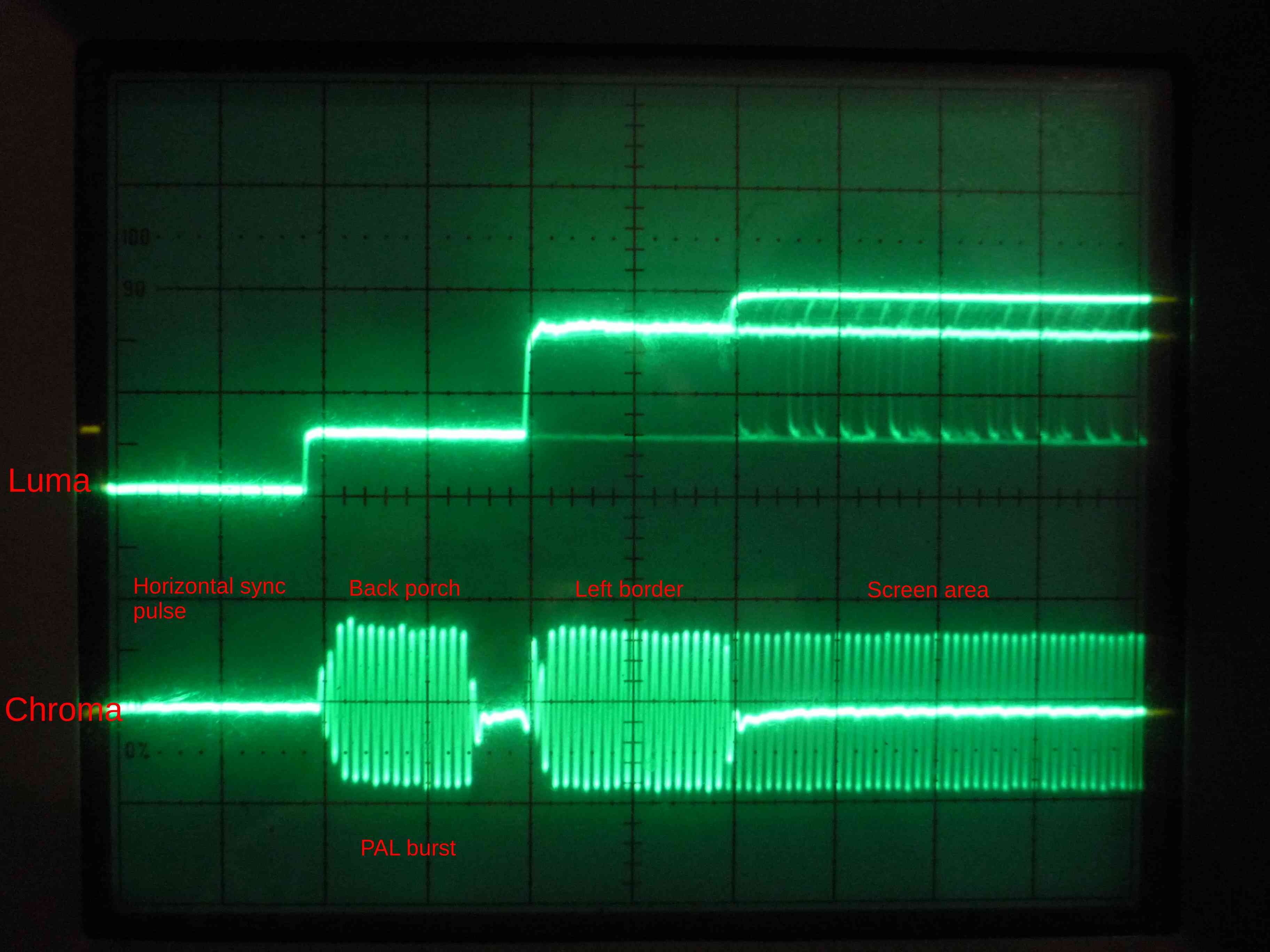
Note the differences. On the stock machine's Luma, there's a noticeable crosstalk everytime the Chroma signal is active. After the fix, Luma is bearably flat at any places (it's not perfectly flat, there's still a bit of noise from the internal signals of the machine, but there's at least no apparent chroma crosstalk anymore.)
And finally, one particular way to fix this.
This is a slightly different PCB than what I've shown before (this is an earlier, Assy. 310163 type, my "work horse" Plus/4's motherboard).
Stock looks like this:
and then there's a small piece of wire soldered to FB7's pins, effectively bypassing it.
I think that's all about it.
One final note: the situation would be similar WRT an NTSC or PAL-N machine. (Pattern looks a bit different, but the overall look is similar.)
|
|
Posted By
MMS
on 2023-07-09
14:24:40
 | Re: Luma / Chroma crosstalk fix
@TLC Thank you for the clear description of rootcause, evidencies and the easy solution (with photos)
I think even I can do it, so anyone can
BTW I think if I take a clear copper wire, and twisting it on the leg of the diode (generating a short circuit), the current will go though that line, so the effect is the same (OK, on the lorn term it will oxidize, so the soldering material is a better method, I just wanted to help the ones do not have soldering iron at home)
|
|
Posted By
MIK
on 2023-07-09
18:05:22
| Re: Luma / Chroma crosstalk fix
@TLC Wow! With the hack your Luma line looks a lot more stable on your scope, and more importantly the vertical bars are gone from the Plus/4 screen! Great Detective Work!!
I think you have more than convinced me to give my main C16 & Plus/4 machines the snip! Cheers!
|
|
Posted By
Phoenix
on 2023-07-10
18:35:43
 | Re: Luma / Chroma crosstalk fix
@TLC Thanks for posting this!
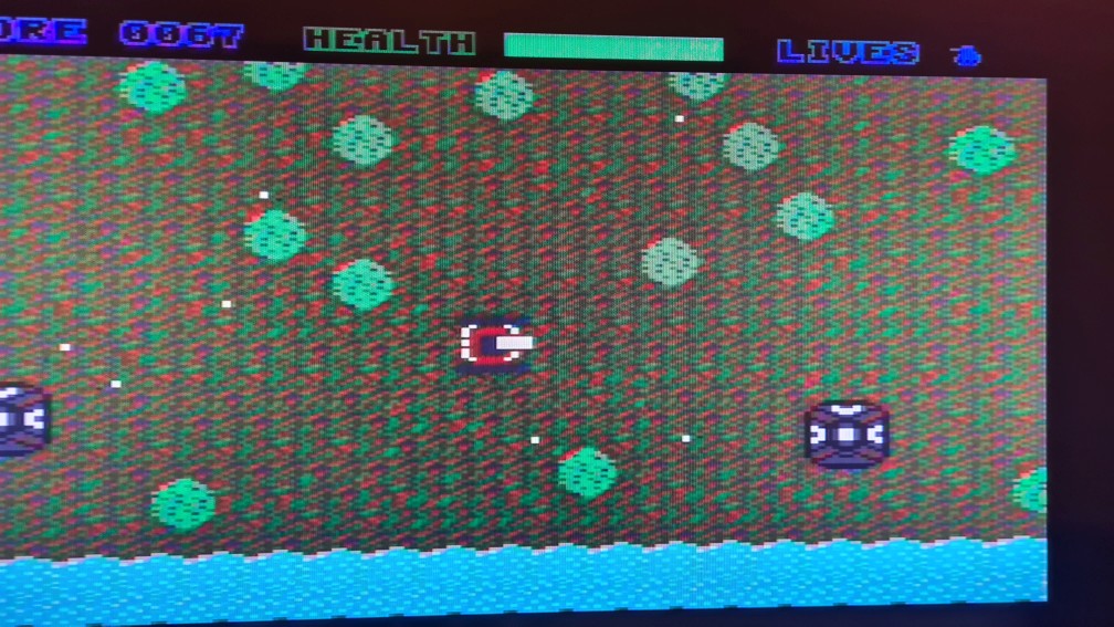
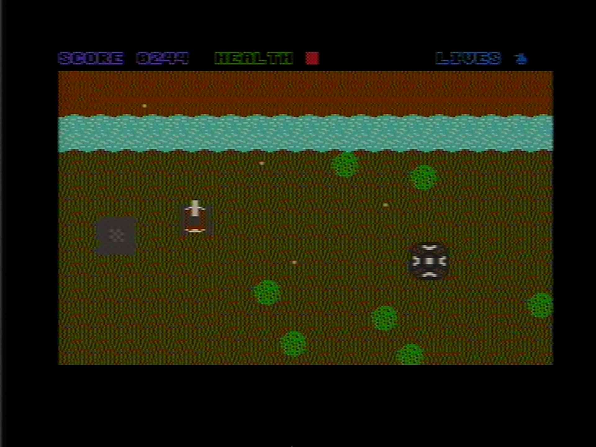
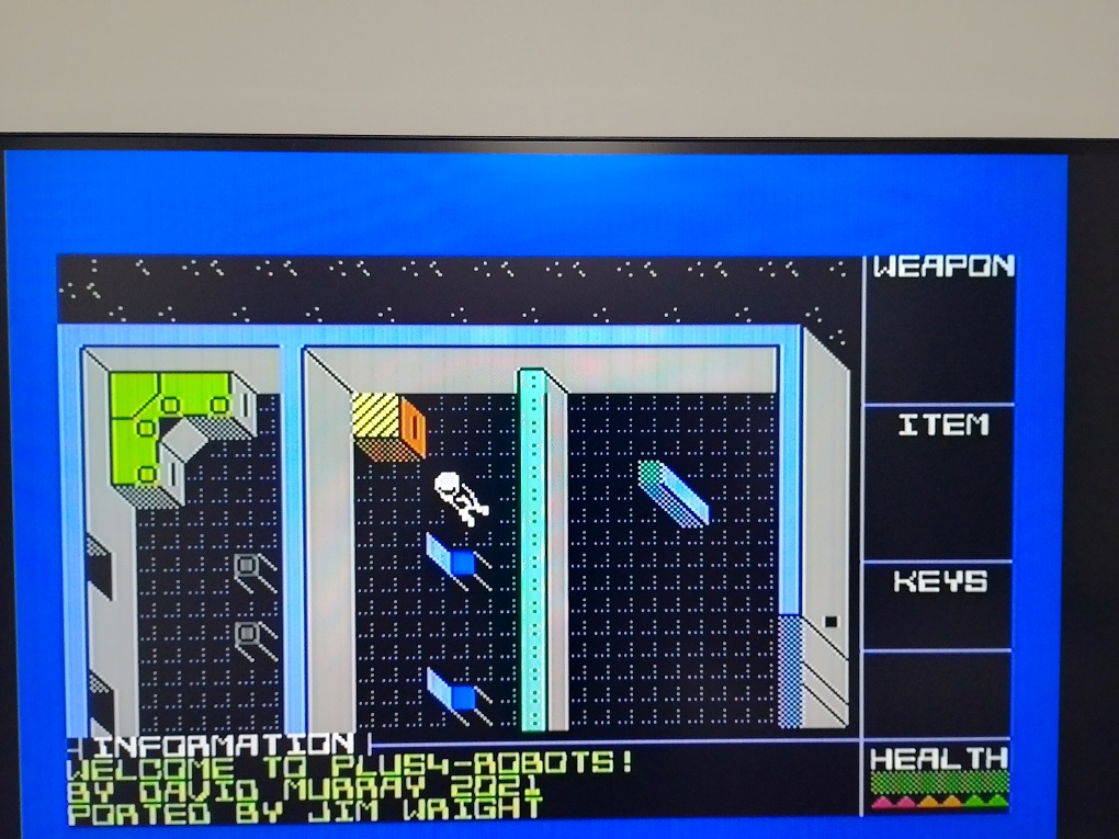
I will have a look at my board later, though I wonder if the artefacts I am observing are solely due to the chroma crosstalk, as it is ways uglier / stronger than on your pics. I notice some purplish color on your composite video photo (letters M of COMMODORE), though composite is another bitch.. I also use s-video, with that these artefacts are less obvious by default. Let me show a short video of a little game I've been developing, the background pattern is badly "flashing" when fine-scrolling in X direction (Y is all fine). Do you think this is the same issue, might be just "bad" pick of colors which make it look worse? In YAPE or P4emu the screen is all clear.
https://drive.google.com/file/d/1GeLIwjfURbxVnXvC5c6Wh__yFBIiFCsv/view?usp=sharing
|
|
Posted By
TLC
on 2023-07-11
07:38:46
| Re: Luma / Chroma crosstalk fix
Thanks, guys!
@Charles I couldn't answer your question, I might only give some background and clues.
As you can see on the oscilloscope captures, luma is a baseband signal, but colour is not. (In a nutshell, the U and V colour difference signals are modulated onto a 4.43MHz carrier with QAM, more about that in the PAL and NTSC standards if you're interested). This is what they call a composite colour (composite chroma) signal. This setup (i.e. baseband luma, and carrier modulated chroma) has a couple of consequences.
1.) luma and chroma behave slightly differently. You can roughly think of the TV picture as a black and white (luma) overlay floating on top of a colour tone (chroma) background.
2.) Chroma's resolution is worse than that of luma. Pixels can have unique luma (unique brightness), but they can only have slightly common chroma (colour tone) with neighbouring pixels in the X direction.
3.) With regards to the Plus/4, the TED produces video output with luma to chroma phases fixed to each other. That means that 1.) there are fixed positions where pixels can be shown, 2.) there are fixed "colour slot" positions for chroma, and 3.) due to chroma having less resolution than luma, the two grids don't match each other in the X direction. In average, there is one colour slot for every 1.6 luma pixel slots for a PAL Plus/4 (in NTSC it's 2 pixels). If you scroll the screen horizontally by an 1-pixel resolution, the content's luma alignment vs.chroma background constantly changes. (I believe, this is the root cause to the effect @MIK was referring to earlier, with regards to RF, in his original thread. But I've yet to set up the really old colour TV set to see... and maybe capture.)
4.) Chroma needs to be demodulated before displaying, and there can be great differences amongst displays, as to how (...how well) this demodulation job is actually done. Smooth colour transitions are usually fine, but huge transitions can impose a challenge to some implementations, where, transition lines may have banding, false colours, anything. Similarly, there can be also artifacts around no-colour to coloured transitions (and vice versa), which is - practically - just also a sudden change in colour. Some implementations behave better to all that than others in practice. Then, already inferior demodulation results can be made even worse by "so-called" "enhancement" processes implemented in modern displays. In my experience, analog colour demodulators usually do a superior job to those implemented in modern digital displays. (That one might have something to do with the fact, that digital displays do colour demodulation and picture composition in the digital domain, on samples of limited sampling frequency.)
So, getting back to your video - yep, as you said, the colour artifacts and flashing can be hardly explained by chroma to luma crosstalk here. There could be some fine vertical banding out of that maybe, and a small bit of flickering with the screen moving (due to the vertical bars' positions changing), but not the colour outlines and blurs. (Note of warning: theoretically, Luma also crosstalks to chroma in the stock setup a bit, so, I said "theoretically", sharp luma transitions can result in a bit of chroma distortion too. In practice, I've never seen this "pronounced" (it was never so apparent than how chroma crosstalk to luma is), but who knows...) In digital displays, further questions arise due to the displays' nature of resampling the source signals, and doing signal processing on them in the digital domain. That can yield unexpected results depending on the sampling's and the picture content's phase - which, in your case, constantly changes while you X-scroll the content.
All in all...
Looking up and getting rid of any screen "enhancement" options in the display's menu, might generally help. (In my experience, usually the most basic setups give the best results here.)
For me, the "rainbow" coloured blue characters in the status line especially suggest that there's something weird going on around the colour demodulation process, especially that (judging from the screenshot you also shared) these characters are just supposed to show in plain blue. This surely can't be explained by chroma to luma crosstalk, and if someone asks me, not even luma to chroma crosstalk to this extent. Unless the connection schema is wrong (say, the display's chroma input happens to be fed from the computer's composite video output by mistake, just to name one possibility), this has to be entirely due to the display's (inferior) method to demodulate the colour signal. You could possibly get a clue, say, by using a different display for a test. That one can be a CRT display, another digital display, or, a PC video capture gadget, no matter which one, provided that they have s-video input. Also, if you put together and share some small example code that triggers the problems that you see, I can also try and capture the results on my setup (I mean the digital / PC involved one above) someday.
|
|
Posted By
Phoenix
on 2023-07-21
18:19:41
| Re: Luma / Chroma crosstalk fix
Hi @TLC,
Sorry for the late reply, there have been lot of things going on in parallel.. so called life :@
Thank you for the detailed explanation, I think you really nailed it. I would not say I completely understand the signal generation part, but I do understand the challenge here with luma and chroma. Actually I do 2 pixels horizontal scrolling (so sprites can stay in place without shaking like in Alpharay) but this obviously does not help with the issue.
I do not have a CRT TV/monitor, my Sharp TV is from ~2000, it has some basic digital processing, I turned it all off but with no luck, it caused no visible visual difference. Actually / usually it displays all +4 content brilliantly, I think I have really managed to create a worst case scenario with these test graphics and color combos 
I may temporarily disable the FLD effect (differential Y fine scrolling), but I don't think it has anything to do with this issue.
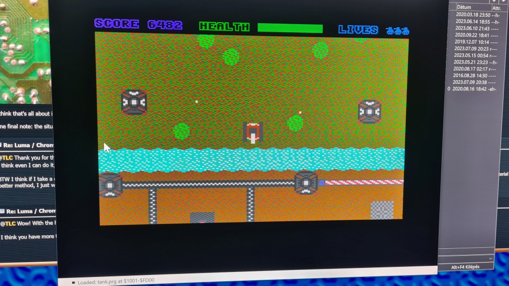
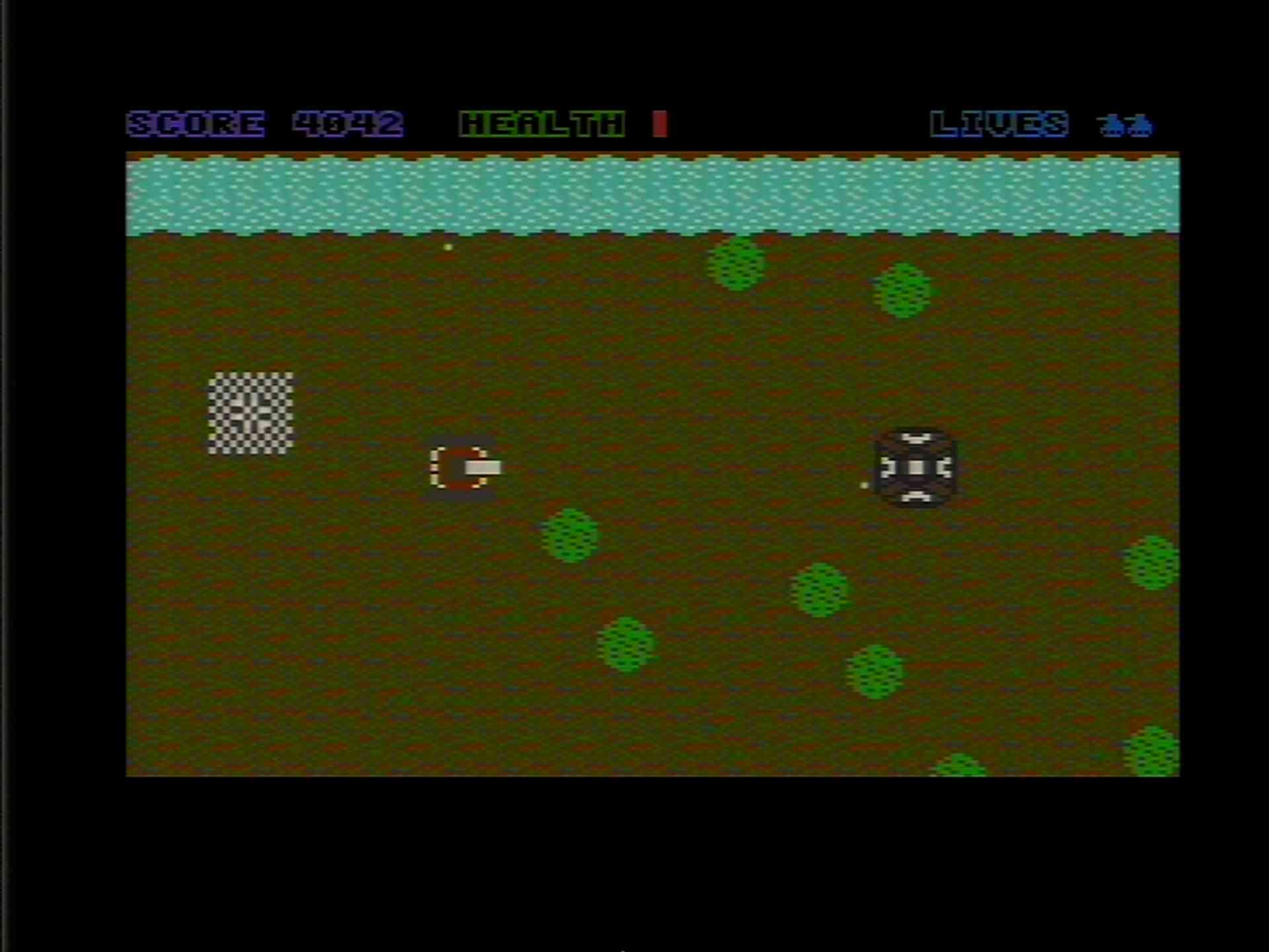
The status bar indeed should have pure purple Score and blue Lives parts, indeed it's a bit strange.
I have just tested with an S-video to HDMI converter using the same TV and a more recent LCD monitor, on the monitor it clearly looks better than the result I shared on the video (though also more blurred), still not a good treat for the eye, some flickering, vertical bars are visible, but no major color flashing or artefacts. This is the point where bypassing that FB filter might help. (?) So this must be indeed my display's signal processing at the end what made it look that bad..
I will send a link to the PRG in a private message, I would appreciate if you could run on your setup and advise how it looks/behaves on a CRT display (should you have one).
Thank You!
|
|
Posted By
TLC
on 2023-08-03
18:51:51
| Re: Luma / Chroma crosstalk fix
Hey @Charles,
Finally got around to try the thing.
I'll yet to have another go, using the CRT display. (I still don't know how I'm going to take useable photos of the CRT, but... anyway.) These images below were produced using the video capture method, like in the previous test. (Plus/4 --> (separate luma/chroma video) --> analog video decoder --> (analog RGB) --> scart video digitizer --> (HDMI) --> HDMI capture device --> PC. (Signal types in brackets.) ).
The results look interesting I'd say.

Interestingly, I can clearly see the chrominance smearing on the status bar text here as well. I could hardly explain the effect right now, TBH. (In PAL, there's always a bit of colour "averaging" both horizontally and vertically. Yet, in the case of some-specific-colour-on-black, like this example is, IMHO the transitions are supposed to vary in saturation only, not colour tone (since, black is zero colour). Maybe I'm just wrong here, I don't know. One thing is sure, the effect is there indeed.)
I made another screenshot, after switching to composite video, just for curiosity. (Plus/4 --> (composite video) --> analog video decoder --> (analog RGB) --> scart video digitizer --> (HDMI) --> HDMI capture device --> PC). The result looks significantly worse I'd say.
Maybe, the effect looks a bit exaggerated here, it's maybe not this pronounced on regular CRT displays. (The capture thing digitized the RGB picture in full HD, which, compared to standard old analog video, is a lot of resolution. What's in there, would be on this picture in full detail). Long story short: composite video is luma + composite colour mixed together (with applying a bit of pre-filtering to luma first). Before displaying, composite video has to be separated back to luma and chroma. This is done by a so-called "comb filter" (there are multiple options actually, comb filters are the most common in analog TV's). This separation thing is not an exact process, there's usually a bit of signal distortion and loss of detail here and there. (It works quite well for usual TV content, less so with "sharp" computer video.) There's yet another possibility, that my analog converter box is simply bad at doing that step (there's quite noticeable chroma residue, something I wouldn't have expected to this extent). At least, the general character (the general direction of how composite video differs from separate luma / chroma in general, with maybe a bit less moire and more blur in practice) is there.
|
|
Posted By
MMS
on 2023-08-05
06:34:23
| Re: Luma / Chroma crosstalk fix
@TLC Thank you for all the detials and the improvement solution.
You just explained now, that due to the previous activities in the C16, the Chroma and Luma cannot be clean enough on the Video Out connector, as they were already mixed together previously. Comb filter cannot do a perfect job, I agree.
But the TED chip produces these signals separately from each other.
Is there no way to lead these signals to a small circiut and after that lead them DIRECTLY to the Video Out connector (eg. with alligator clips)? I know these TED signals, and especially the open drain signals cannot be used like this (also: would be an additional ESD risk to our TED chip), but with the help of some protective components, and with a piggypack circuit, lead directly use these TED signals (eg aligator clips )after lifting these legs from the PCB (I mean the video our t connectors)?
These should be crystal clear without any disturbance and interference.
BTW this circuit can be switched to switch between the Commodore 1V PtP level (needed by the Commodore monitors to provide the right picture) and between the SVideo standard (0.7V PtoP signal)
Hopefully you understand my question...
|
|
Posted By
SukkoPera
on 2023-08-05
08:42:56
| Re: Luma / Chroma crosstalk fix
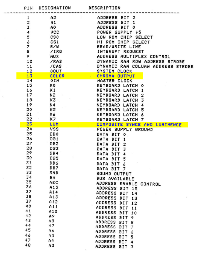
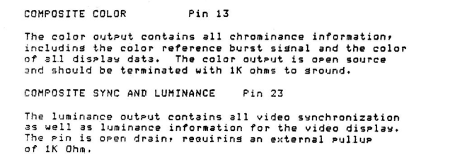
Unfortunately the Luma and Chroma signals coming out of the TED must be amplified and buffered before they are usable. These things are done inside the modulator in the original machines, which probably messes things up a bit while it does the RF magic.
In LittleSixteen we have removed the modulator and replaced it with the minimal circuit required to do so, deriving it from the modulator schematics:
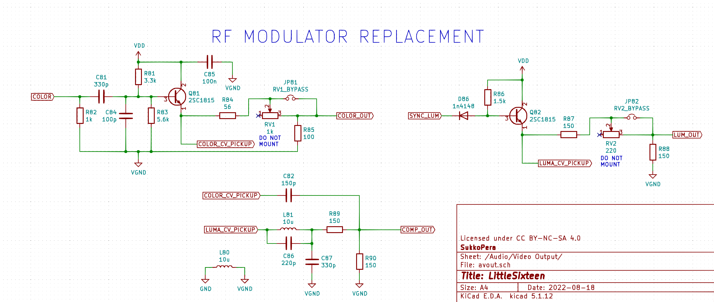
V3 already had a good quality (someone wrote to me saying he was surprised at how good it was). In V4 we have tried to do even better, using a separate ground for the amplifier circuit, adding a few decoupling caps and changing the routing of the tracks carrying the Luma and Chroma signals so that they no longer pass between pins of the TED and are separated by a strip of ground from any surrounding tracks. Of course we have also removed FB13! We'll see how that works out .
Of course it's not easy to do those things in an original machine, but at least Edoardo has designed a board that can replace the modulator, removing all the RF mess and keeping the A/V connector working while adding an S-Video connector, all of which should vastly improve the situation.
|
|
Posted By
MMS
on 2023-08-05
09:36:42
| Re: Luma / Chroma crosstalk fix
@Sukkopera Thank you, it was the information I was looking for
|
|
Posted By
Phoenix
on 2023-08-10
15:40:11
| Re: Luma / Chroma crosstalk fix
@TLC,
Thank You for testing (and sorry for the late response), I don't think it's your converter to blame, or then it is pretty much all converters. I have a relatively good one (S-video to HDMI) and though it looked a bit better than the TV embedded one, both were really barely acceptable quality. Did you manage to test it on a CRT screen in the meantime by chance..? I am curious about the results, though I'm afraid the color choices are to blame here, this really seems to be a limitation of the design.  I deem to see the artefacts on your screenshots as well, was the background also "flashing" for you when moving horizontally? I deem to see the artefacts on your screenshots as well, was the background also "flashing" for you when moving horizontally?
@Sukkopera 's RF modulator replacement looks intriguing, I wonder how difficult it is to install in an original +4. Does anyone here have experience with it by chance?
|
|
Posted By
SukkoPera
on 2023-08-10
16:37:31
| Re: Luma / Chroma crosstalk fix
I've never installed it, but installation should be easy. It's removing the modulator that might be tricky, you probably need a very good iron and a higher-than-usual temperature.
|
|
Posted By
Imperious
on 2023-08-19
06:51:13
| Re: Luma / Chroma crosstalk fix
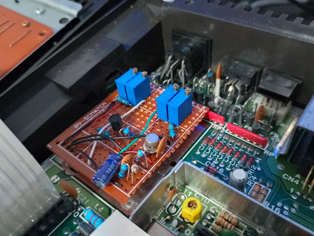
I removed the rf modulator in my plus/4 and made up circuit above on a piece of vero board. It looks like something out of a 1970's amplifier but has definitely improved the video quality. I am using one of those cheap nasty s-video to vga converters which then runs into a cheap passive hdmi converter. I have a Retroscaler2x on the way so should be interesting to see what if any further improvements will be seen. Actually most of the parts were in my c64 before I replaced it with a copperdragon component pcb.
|
|
Posted By
SukkoPera
on 2023-08-19
11:41:33
| Re: Luma / Chroma crosstalk fix
Well done! One caveat with that circuit is that you should stick to the indicated values as much as possible. I know many are uncommon values, but at a first attempt we had tried to use different, close values and the final quality was not the best.
I think many of those could be recovered from the old modulator, if it can be sacrificed.
|
|
Posted By
Imperious
on 2023-08-19
22:31:38
| Re: Luma / Chroma crosstalk fix
The resistors and capacitors are the exact values from the schematic above. I had some different values beforehand but it didn't work properly. The pots are on the outputs and are just for tweaking purposes.
|
|
| |
Copyright © Plus/4 World Team, 2001-2025. Support Plus/4 World on Patreon |