External User Port for the C16: Let's make it! It seems that many have tried but no one has managed to create a cartridge that adds a User Port to the C16. At least I couldn't find any open design for one.
So why not work all together to finally make one? There are a lot of HW gurus here, I'm sure we can do it!
I have done the first step, i.e. I have drawn some schematics, taking inspiration from the Plus/4 docs and other sources. Now I need your help, to double check what I have done, answer the many questions I left there and question the choices I have made.
In brief: - Both parallel and serial ports - Onboard RS-232 converter (MAX238 so that we can convert *all* the signals) and DE-9 port - No 9VAC on the port but never mind (and the MAX238 doesn't require it) - /CS generation through a GAL as on Solder's SIDcard
I used the standard MOS 6529 for the parallel port, but since that is not exactly common these days, I would like to include Daniel Mantione's circuit that replaces it with a 74x652 or 654. I couldn't find any schematics for that though, is he registered on the forum?
Please note that I am fully aware of the D2/Cassette Sense problem that prevents us to map our user port to $FD10, but let's leave that aside for the moment and focus on making something that will work at another address at least. I have chosen the same addresses that Solder was going to use in his attempt, but of course those are negotiable. Once we get something working, we can discuss on what to do regarding the Cassette Sense issue.
My schematics are available here. Please note that I plan to license the final work under CC BY-NC-SA 4.0, only contribute if that is fine for you.
Re: External User Port for the C16: Let's make it! Not sure if Daniel is reading here, but he's active on forum64.de as dmantione. I can also write him and point him to this thread if you want.
Re: External User Port for the C16: Let's make it! There was a topic discussing the very same thing a while ago. One participant clearly stated with thorough reasoning there that it is not possible to create an external replica of the Plus/4 User Port for the C16 that is fully compatible with the original.
My question is: What would be the point of making an incompatible extension that blocks the Expansion Port?
Re: External User Port for the C16: Let's make it! I think I know what topic you are talking about, and there the conclusion is that it is impossible to create an external replica of the userport that sits at the Plus/4 address and that is because of the D2/Cassette Sense issue I mentioned earlier. Besides that is only true for the parallel part of the port, I think the ACIA can be added with 100% compatibility.
As far as I understand there should be no problem in making a userport at another address and that is what I am trying to do. There are reasons for that: - Software can just have a configurable userport address - Understand how we can circumvent the D2 issue and come up with a modification for the C16 (the least invasive modification possibile, I already have an idea) - Build the modification into my LittleSixteen project - Have multiple userports, even on the Plus/4 - Documentation - Fun
Re: External User Port for the C16: Let's make it! Hi guys,
First post here on this forum. I am certainly willing to share my 6529 schematics, I'll get back to this quickly. It's quite simple: A 74x402 that generates the control signals for a 74x654. If you are already using a GAL, you can consider to use the GAL to generate the control signals and remove the 74x02.
About the cassette sense problem, main issue I see is that it activates both for reads and writes to $FD1X, if it would have been read-only you could have decided to use the existing circuit for reads to D2, but any write than the 74x125 on the C16 mainboard will cause a bus conflict.
You could consider to solve the cassette sense problem with a custom PLA that doesn't decode $FD1X. It'll cause some cassette compatibiliy issues but then you can make the user port cartridge fully compatible. It's a pity that none of the TED PLA lines are connected to the cartridge port, otherwise it would have been far easier to create an elegant solution.
Re: External User Port for the C16: Let's make it! Hi Daniel, thanks for joining the effort! Thanks for willing to share your schematics. Yeah, of course the circuit is not rocket science, but generating the correct control signals for the enables and direction pins might have pitfalls, and since you must have already debugged that, I would definitely avoid redoing it very gladly .
I have quite a few interesting news about the Cassette Sense/D2 incident, let me finish the testing and then I'll share them. I will probably open a dedicated thread since this whas implications that go beyond adding a user port to the C16 (Spoiler).
The thing that puzzles me the most with the Plus/4 schematics I replicated is why some signals get inverted between the ACIA and the RS-232 transceiver. I know that the RS-232 protocol inverts signals, but that should be merely a transmission concern and signals between the ACIA and the MAX23x should be exchanged at the "original" levels, as far as I understand. Can anyone shed some light on that?
Re: External User Port for the C16: Let's make it! In the 6551 datasheet, the RTS, DTR, DSR and DCD have a line above them, which means they are active low. Could it be that Commodore's VIC-1011A expects them active high, so they had to be inverted to be compatible with the VIC-1011A?
Re: External User Port for the C16: Let's make it! Yeah, all the RS-232 control signals are active-low on the TTL-level side, which results in a "high" (+15V) level on the RS-232 line. This is the norm, as far as I understand, but now I find out that all Commodore modems (including the VIC-1011A, I guess) have always used reversed RS-232 levels (TTL low -> -15V, TTL high -> +15V). I can't find any exact source stating this though, but there are several allusions all around. VICE also a lot of options to toggle the inversion of each control line.
So well, I guess that sort of explains the presence of that inverter gate, and I will have to get /CTS through it, too. I'm really tempted to add jumpers that bypass it though!
Re: External User Port for the C16: Let's make it! I have read a lot of points already said in the thread, I'm just gonna add some 2 cents.
- As you're already well aware of that, the guys had pretty much messed things up by misusing one port bit of the 6529B SPI for cas sense in the Plus/4, and the equivalent address space in the C16/C116. This is clearly a (dirty) hack. (But this detail makes things no easier...)
- CTS' was disconnected and rerouted in the original Plus/4 design for a reason. The CTS functionality of the 6551 is buggy. Dropping this control signal causes the 6551 to stop transmitting immediately, I mean it'd asynchronously disable the transmitter in the ACIA. That is, whenever the opposite party says "please stop transmitting more bytes", the byte currently being transmitted would be immediately broken. Reverting this part, i.e. CTS to be fed from the 6529B rather than the 6551, appears IMHO a good idea.
- That'd probably also mean that working around the $FD10 thing is unavoidable, if full compatibility is desired someday.
- About inverted / non-inverted control lines: the Plus/4's user port layout mimics the earlier Commodore machines' user ports, which implement inverted TTL RS-232 control lines. (Those machines have no physical ACIA onboard, they "emulate" this functionality from Kernal routines and bit-banging.) If you check either the VIC-1011A as you already have, or, check some popular replacement say GGLabs' GLINK-LT https://gglabs.us/node/2044 you'll see that both of them uses inverters to invert the control lines. (About the same way as you did in your design BTW.)
- One particular thing I'd be suspicious about in a hybrid design (i.e. a user port + permanent rs-232 line transceiver combo), is user port backwards compatibility. That is, to make sure, that the rs-232 line transceiver part never interferes with "standard" user port functionality as long as the rs-232 port is free. (Considering that both the '04 inverters and the Max chip have Totem Pole outputs, currently I'm not sure if/whether that part suffices).
- I think the limit here would ultimately be current consumption, especially if 9VAC capability was to be added someday. The power supply part of the C16 / C116 is particularly... errr... "interesting", and weak.
Re: External User Port for the C16: Let's make it! Thanks you too, Levente!
The /CTS handling being broken in the 6551 is interesting. Do you know if that has been fixed in the W65C51S? Anyway the jumpers in my schematics should already allow for putting /CTS on the 6529, by putting both JP2 and JP3 in the bottom position. Do you agree?
Consider the $FD10 thing fixed. It requires a mod inside the C16 but it's a very easy one (both to do and to undo, I like reversible mods). It's a hacky way to workaround another hack, but it seems to work very well. More on this later (need to test one last thing)!
OK, I finally understand the purpose of the inverted signals, but that actually means I have to *remove* the inverter from my design, if I understand correctly. The GLINK-IT is connected to the userport, and the signals there have already been inverted by the onboard 74x04 inside the Plus/4 (check schematics), so it has to invert them again before they are fed into the MAX23x, in order to "rectify" them. In my design the MAX23x is connected directly to the ACIA, *before* signals get to the userport, so they shall just be connected straight. Does that make sense? Even if it would imply that cables like this are incorrect, as they lack the inverter (Unless software compensates for that)...
EDIT: The QuickBasic program in the docs for that cable opens the COM port with options "CD0,CS0,DS0,OP0,RS" which actually turn off all control signals, so that explains why it works :).
Yeah, the MAX23x will definitely drive the signals on the userport even when just sitting idle. It doesn't have an enable pin so I can't do much about it (well, I guess I could add an 74x244 inbetween but I'm not sure there will be enough space on the board). In fact I was skeptical about connecting the serial pins to the userport but then I did it as I feared there was some odd userport peripheral out there that used serial pins for out-of-band signalling on the userport besides transferring parallel data through the 6529. So I added that note about having to remove the MAX23x from the socket in this case. Has anyone ever heard of such a peripheral?
Re: External User Port for the C16: Let's make it! Most (or all?) Plus/4 computers have the 8551 rather than the 6551, so we also would need to know if the 8551 has this bug.
Re: External User Port for the C16: Let's make it! Thanks a lot! Will have a look at it ASAP!
EDIT: Had a look and I think I can integrate the generation of the signals if I switch the GAL to a GAL20/22 (or if I sacrifice the address configuration jumpers).
OTOH, your other candidate i.e. the W65C51N https://www.westerndesigncenter.com/wdc/documentation/w65c51n.pdf is probably still buggy (as far as CTS is concerned). At least, the datasheet says that "The CTSB input pin controls the transmitter operation. The enable state is with CTSB low. The transmitter is automatically disabled if CTSB is high." and nothing more. Pretty much the same what the original 6551 datasheet says.
Sure, the jumper option should be fine.
(Footnote: IMHO it was pretty easy for the guys not to get this correctly in the original ACIA design. AFAIK CTS/RTS handshaking wasn't common until the PC's came around i.e. by the mid '80s. In previous / original practice, when CTS dropped it pretty much meant that the opposite party was gone for good... that is, some corrupted last byte really made no difference. On a related note, if you take a closer look at the VIC-1011A schematics, you might notice that it looks ancient, compared to any RS-232 setups we know from PC related experiences. This is all pretty much from a modems / terminals / dialup TTY accesses etc. (pre-PC) era. ...But at least the guys already got the CTS thing right, as far as the Plus/4's design is/was concerned .)
In my design the MAX23x is connected directly to the ACIA, *before* signals get to the userport, so they shall just be connected straight. Does that make sense?
Oh yes, sure. (Sorry, I always get lost after a couple of signal inversions :-/ ). BTW, there used to be a C64 6551 cartridge, the CMD SwiftLink, which was once "cloned" to an open source design called "DataPump". It's basically also a 6551 + MAX*** on a cartridge... albeit for the C64. http://www.zimmers.net/anonftp/pub/cbm/documents/projects/rs232/datapump2.zip . And it's practically doing what you suggested, i.e. no inverters are used.
Has anyone ever heard of such a peripheral?
The SP337E https://docs.rs-online.com/94ca/0900766b80f6c005.pdf appears to have output enable capability for the RS232 receivers... and I vaguely remember some (albeit rare..) other examples from the past... But, yes... things are getting a bit esoteric from that point on.
Re: External User Port for the C16: Let's make it! OK, great news . The MAX239 has an enable pin and and extra receiver driver which would allow us to do something with the RI pin too, but unfortunately it requires a second powering voltage > 7.5V which we don't have. The MAX235 would be fine too (it would even require no external caps!) but unfortunately it's nowhere to be found. The SP337E is SMD and for the moment I'd like to stick to THT stuff, otherwise the MAX240 would be another possible choice (a DIP version is mentioned on the datasheet but I can't find it anywhere). So I guess we'll have to cope with the 238 for the moment. I really don't get it why there are so many MAX2xx chips and none seems to have all the features to handle a standard 9-pin serial connector (Well, actually the 235 did, maybe it was too expensive?).
Anyway, I am now trying to integrate @dmantione's 6529 replacement, hopefully I will be able to make everything fit. I will have another couple of points after that is done and then I guess it will be time for prototypes!
One of the clocks on the cartridge port can be used as clock signal. Don't use it directly but run it through a MOSFET inverter, because the energy required should come form the 5V line and not from the clock line.
Re: External User Port for the C16: Let's make it! Sorry about that dmantione; the forum engine was overzealous and replaced "colon D" with a grin emoji, right in the middle of the link :-/ (I'll fix that today.)
Also, I just want to say that I understand none of this, but I love reading the high-level discussion, and of course you have my spiritual support
(Edit: that bug in the forum engine has been fixed.)
Re: External User Port for the C16: Let's make it! @dmantione: Thanks for the tip, but I think I'll stick with the 238 for this first prototype. We'll see how well it works .
@Csabo and @Luca: Thanks for the encouragement! I must admit I'm pretty confident we'll get somewhere this time!
On a side note: Can you somehow add the possibility of adding images to posts also during Edits? It seems to only be possible when doing a new post, at the moment.
Re: External User Port for the C16: Let's make it! @SukkoPera: hah! So you don't have a clue that Csabo some months ago had success in forcing into this old shaped homepage a super smart feature for the inclusion of the images into ahread!
Just drag 'n'drop your chosen picture into the text editing window, and magically it will be uploaded, automatically becoming a very oldschool HTML string ready to be posted into your text!
Re: External User Port for the C16: Let's make it! @Luca: That's exactly what I meant: that neat feature seems to only be available when writing a new post, not when editing one that was written before!
Re: External User Port for the C16: Let's make it! That's unfortunately not an easy change due to how the code is structured. Otherwise, it's still doable, just a couple of more clicks: upload your image via the Site Uploader (first link under Features), which gives you an HTML tag, ready to be pasted into your edited post.
Re: External User Port for the C16: Let's make it! You have the diodes pointing in the opposite direction as I do.
Further, the 8.2K resistors should be placed if a 74x654 is used.
Lastly I wouldn't recommend standard diodes like the 1N4148, because you want to pull the output as close to 0V as possible. I'm using BAT54 Schottky diodes in my design, if you want a through-hole diode, I propose to use a BAT43.
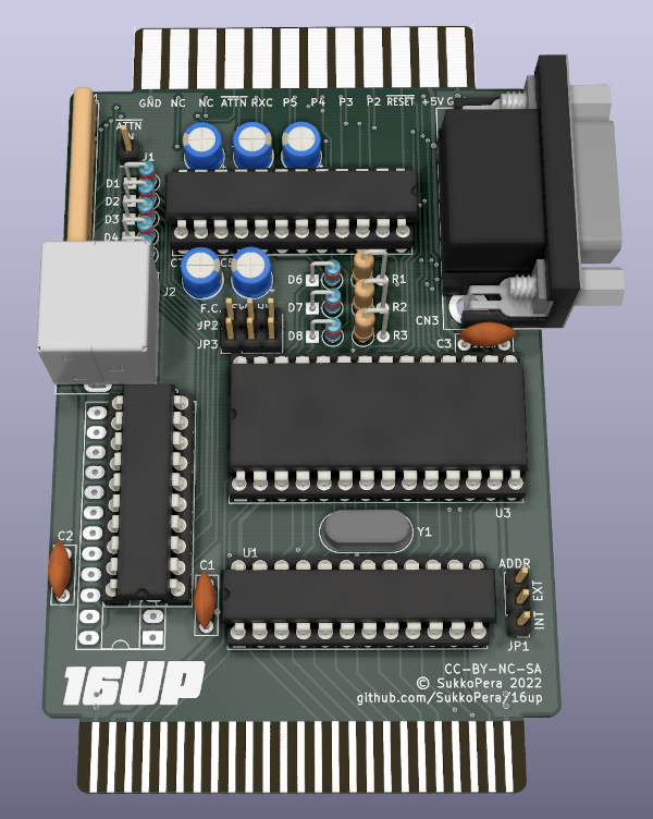
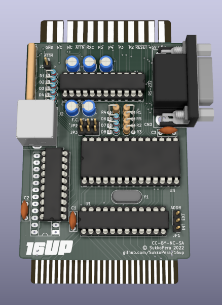
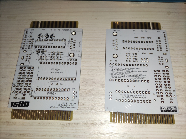
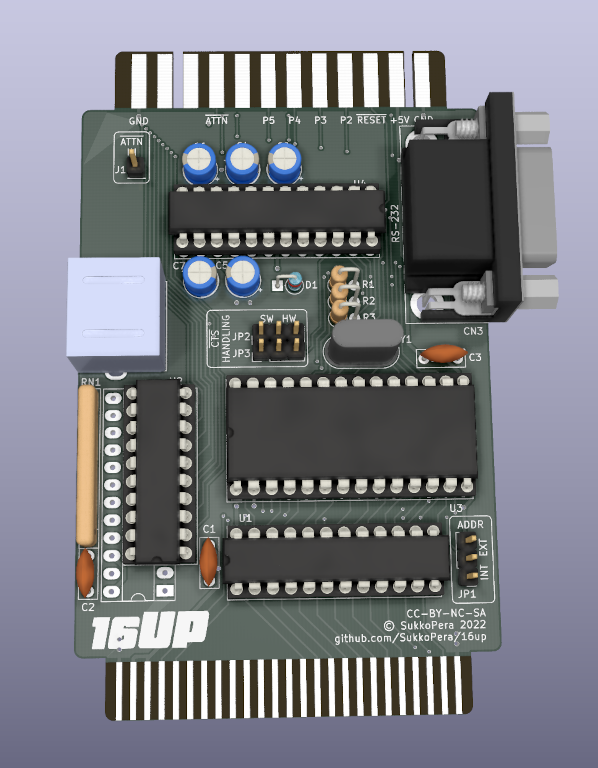
Re: External User Port for the C16: Let's make it! OK, of course it turns out that the only bit I had recycled in the design that I hadn't double checked was totally wrong: the user port connector itself had inverted pads, the wrong pitch and the wrong width. Luckily I noticed before it was too late. Here's the final look, not too different from the above actually, unless you squint a bit .
This is probably my worst placement and routing ever but well, I hope it'll just work. As I think the design is now complete, I have also published the final schematics. Actually I have even made the whole project available for those who want to have a look.
I have also finally written a short essay about the modification that will be required to make this board work. Please check it out and let me know your comments!
Re: External User Port for the C16: Let's make it! Wow! Respect! An extraordinary hardware discovery. Possibly an answer on why the CPU always tends to fail.
If I understand well, this hardware bug is only fatal when a key of the datasette is pressed down while starting up the C16.
It would be well worth a longterm examination: is the CPU lasting longer with your modification?
A further question: how does this corresponds with the CPU's of Pjotr Bugaj (FPGA) and Max Massimilano(6502 based). Did they bypass this bug?
Re: External User Port for the C16: Let's make it! Well, this could certainly be a failure cause for CPUs on C16s in the long run but we are seeing dead 8501's on +4s as well, which do not present the problem, so there are definitely maaaany other causes. Since it is a quick mod though, why not just do it and eliminate one cause?
The problem can be triggered anytime by issuing a certain POKE command, and it also happens "automatically" at power-on or reset if a key on the Datassette is pressed down.
I am not sure if the available CPU replacements do anything in this regard. They can sort of protect themselves by putting a series resistor on D2, but that placement is not ideal (It would still not compatible with the userport, for instance). The best choice is to put the resistor between U11 and the data bus.
Re: External User Port for the C16: Let's make it! Wow, 1) great achievement! maybe I lost somewhere the information, but does it mean if you connect a Max232 circuit to the new user port, you can read the same way the serial data? On the other hand we have that nice RS232 port, but I am not sure about the proper protocol. or at which address? My ideas is around BSZGG's RS232 mouse project, somehow make it standard for the scene (after if works properly)
2) Your cute C16 project with C64 joystick and datasette ports! I am impressed! I will probabbly order one too. I've just mentioned on a FB discussion, that simply those two changes on the C16 and plus/4 could save the range and they could have succeed. I understood, that the tiny C116 could not handle those big connectors in the small housing, but the limitations of the new connectors simply killed the reviews of the 264 range at the magazines. Frankly speaking, the C116 was useless with the soft rubber keyboard for the main task: programming. As it was not a game machine, right? Few comments: -It is a smart choice to use the new C64 housing releases in black. This color fits the most to the breadbin shape, and it would cost the least for us . -I also use PCBWay. There are so many nice projects related to C16, just to name few: solderless 64K upgrade, TED protector based on Levente's design, Blutooth joystick interface. -TBH I prefer the C16 jack connector. That's why I think the C16 is the most preferred machine from the range. Why? Because old C64 PSUs are known to kill the machines. The new modern ones are rather expensive, and we do NOT need the full power C64 PSU provides. We have a cute TED, not the power hungry VIC and SID :-) So my point: You can get a regulated 9V switch mode PSU with that C16 jack dirt cheap! It works like charm. C16 power consumption is low (especially with EEPROMS), so 1.0 - 1.5 A should be more than enough. So changing the psu connector to C64 type does not support the product future proof state, just the opposite, you will become depend on special and expensive future C64 PSU production batches. But it is just my opinion. Please do not take it as a crytic, I also use my Plus/4 with a C64 PSU, but I prefer my C16.
-Actually my view is, that a USB port could fully support the C16 aims with a voltage doubler. Certainly I am selfish, because I do not use datasette any more (but the SD1541/II and 1571) On the other hand, a microUSB port, or even a USB-C port would provide enough power and stable enough 5V voltage for the computer. Did I mention dirt cheap wall charger? If you have any smartphone came with USB charger, you do not need to buy anything like this, you simply have the proper PSU (except you bought an Apple iPhone and you did not get a charger )
Re: External User Port for the C16: Let's make it! Thanks for your kind words!
1) I'm not sure what you mean with "read the same way the serial data". You could plug a classic MAX232 Plus/4 serial card to this board, but why should you? That card is already embedded in this board, you can just plug your serial mouse in the onboard DB-9 connector and pretend you are on a Plus/4 (i.e.: Port address is $FD0x if you put the ADDR jumper in the INT position, $FD6x otherwise). I'll definitely try a mouse as soon as possible on the prototypes!
1b) This got me thinking that plugging an external serial card is actually not going to work, as it will expect inverted control signals, which I'm not providing since I removed the 74LS06. Aaaargh, this was an oversight, and I don't think I can fit the inverter on this crowded board. I think I'll just remove the serial signals from the edge connector for this version, I might reintroduce them on a later board using SMD components.
2) Thanks, don't order anything at the moment, I already have a version with further improvements in the works! As I explained on the Hackaday development blog, I chose the C64 power supply because basically all other Commodore machines (VIC-20, C64, C128 and +4, with some different connectors but same supply voltages) work with it, so anybody who is a retromaniac must have one of those anyway... and a reliable one! There's no reason for them to be expensive, I have my own design for one and it works very well, besides fitting in the original wedge C64 power supply, which is a pro for looks . It uses very few components (like 5), amounting to around 25€ in parts (at least when I bought them, might have increased now - EDIT: Checked, it would probably cost ~50€ now, sigh) yielding up to 4A on the +5VDC and 12VA on the 9VAC IIRC. I haven't shared it yet because I'm not sure it is safe enough for connection to mains power. It is for me, but I'm not comfortable with other people using it (one is, actually, I gave him one as he needed a C128 power supply and couldn't find anything, he's very happy about it but I had him swear he will unplug it from mains every time he has finished using with the computer). We'll see in the future, I guess. BTW using the C64 power supply and connector also means we can fit the new cases just perfectly!
On a side note, the project is open, everybody is free to modify the board and introduce whatever power connector and circuit they like .
Again, thanks for your comments, constructive criticism is always welcome!
Re: External User Port for the C16: Let's make it! @SukkoPera: That 1) mentioned by MMS might be my influence. Although connecting a 'cheap' serial mouse to the 264 series machines is a nice idea, I have some issues with that. Those peripherals are slow and their communication is quite asynchronous with the screen refresh rate of the machines. Which would be an enormous hindrance when programming anything that uses raster interrupts and a serial mouse. My idea was buffering that communication with a microcontroller and transmitting mouse data only at request and with a sufficiently high external clock like 19.2k or higher.
Re: External User Port for the C16: Let's make it! May I suggest a C16 "solderless" modify for using an external $FD1X port?
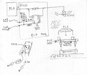
The U11 (that drive D2) gate has to be ALWAYS disabled during WRITE cycles, if required it has to be disabled also during access of external parallel port on $FD1X, so the C16 can be modded pulling out the PLA, putting in a little board (see next picture), reinstalling the PLA and connecting 2 wire (with hooks) to the CN1 expansion port. The PLA and the little circuit can be replaced by a new PLA that do the same (with a CPLD...). On C16 the not used CN1 "BB" pin will become "/EXT.P" input (external port, active low)
The R/W pull up is lite (10K) but the /EXT_P pull up is a little heavy (3.3K), the logic function can be easy done (with little delays) by an half of 74LS139 or by a 74LS138.
The external cartridge can be easily modified as:
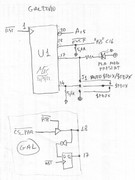
A GAL22V10 has to be used, /RST has to be placed on pin1 (CLOCK input for the internal FF), so the A15 line has to be moved to another pin (20?). During the HW reset, pin 18 (GAL) will be only an input and when the reset line rises the internal FF keeps the information "PLA MOD PRESENT" and presents it to pin 17 (GAL), and a LED will indicate if C16 is modded. Now pin 18 becomes an output: when the external parallel port will be enabled (/CS_PAR=L) the /EXT_P will be L and the modded PLA deselect the internal U11.
Also pin 14 (GAL) has a pull down resistor: if no jumper will be placed it will be "L". J1 can be used for connecting a 3 position lever switch (ON/OFF/ON): OFF: Pin14 will be "L" and the port will be $FD1X (for the previous resistor based C16 modification). VCC: the port will be $FD7X (ok for HW conflict, but not compatible for SW written for PLUS4) AUTO: if C16 is not modify the port it is $FD7X, otherwise it is $FD1X
If tape activity is needed the J1 switch can be placed on "VCC" and after it can be moved: CST SENSE will be lost but external port will be enabled on right address
Re: External User Port for the C16: Let's make it! @gerliczer: What you mean is that you would prefer having a functional TTL-level serial instead of the RS-232 one? That can still be done with my board as it is now, it would actually be even simpler, as it would save you from having to invert all the control signals. That would mean your board wouldn't be compatible with the Plus/4 though, so I'll fix that in the future, just not now in this experimental version as I am eager of testing it .
@MCes: Well, that is something along the lines of what I had in mind for the first solution I talk about in my essay. I did not propose that in the end as it is waaaay more complex than just lifting a pin and soldering it back through a resistor. Do you see any issues with my approach? I would be very glad of having your feedback about it!
Re: External User Port for the C16: Let's make it! @SukkoPera (maybe you read my post before i completed it) "resistor mod" is an easy way to limit current on D2 during an unwanted WRITE operation, but it cannot guarantee that an external MOS6529B will drive H on line D2 if CST_SENSE is L, and there are C16 owner who not can/want soldering on theyr motherboards...
Re: External User Port for the C16: Let's make it! Can you explain why not? My idea is: the 6529 on the expansion port will be directly connected to the CPU and will set D2 low/high. Even if U11 tries to set it to the opposite level, the inbetween resistor will make it unable to influence the voltage the CPU actually sees, which will be what the 6529 wanted. The value of the resistor will keep the current flowing through it to a small value.
I have tested it with a 6529 and it seems to work very well, but I understand I might have been lucky, I might be missing something due to my little knowledge of electronics. Can you please add some detail?
I understand the point about people not wanting to solder something into their C16s, but it can be done easily, cleanly and reversibly, that would be sufficient for me.
Re: External User Port for the C16: Let's make it! Older logic devices can drive lines harder to L than to H. Example: MOS6529B Voh is guarantee for a load of 200uA (0,2mA) but Vol is guarantee for a load of 3,2mA (ratio of 16). http://archive.6502.org/datasheets/mos_6529_spi.pdf
If the CPU is writing, it will be even worse: Ioh=100uA (0,1mA) and Iol=1,6mA.
Immagine that CPU is writing H on D2 with a max of 0,1mA out: (2.2K)x(0,1mA)=0,22V, so the D2 line will rise about 0,22V the L level that is lowered by U11..... the CPU H is lost!
With these numbers, whoever drives low D2 wins ...
It can not be a problem (CST_SENSE is normally H), but someone that has not your "resistor mod" inside could use your cartridge and made a conflict. My solution is more complex but it can sense if the C16 is modified and reconfigurate itself (with a "solderless" C16 modify)
Both solutions have their positive and negative aspects
Re: External User Port for the C16: Let's make it! @SukkoPera: Actually, I don't care about logic levels. What important to me is usability. If a new peripheral is connected to the machine it should not impose additional constraints on programming models and it should keep compatibility with existing systems. If that means TTL-level serial signals then so be it.
Re: External User Port for the C16: Let's make it! @MCes: Thanks, that was exactly the kind of input I was looking for. Now I will have to ponder a bit on what you wrote to fully understand it. I'll get back to you ASAP!
@gerliczer: Then I don't get what you mean. This board will not impose any new constraints. Provided that we manage to get the small mod working, you just place the ADDR jumper on INT, plug the board and... poof: from a programmer's point of view you can just pretend you are on a +4 with a normal User Port and a "standard" RS-232 interface plugged into it. That's an explicit design goal.
Re: External User Port for the C16: Let's make it! @SukkoPera: I have no free time for it, but if someone else can develop a CPLD for you than it will possible to make a good variant inside your cartridge....
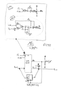
immagine a CPLD with inside: - your GAL (with the PLA modify detector), - the 6529 parallel port, - THE CST_SENSE EXTERNAL READER obtained by "sniffing" the BUS: Into C16 the U11 is enabled during F2=H for hundreds of nS (MOS6529B is not fast...) but if the port is integrated inside CPLD (it answers in tens of nS) there is time for doing this: (remember that if CPU is writing R/W=0, U11 is already disabled by PLA modify)
/EXT.P=H, if $FD1X is decoded by PLA than U11 will be enabled on rise of F2 (F2 = phase2 on CN1 pin24). CPLD waits (50nS?) from rising of F2 and capture D2 (reflecting CST_SENSE state generated on D2 by U11), now the CPLD will drive /EXT_ P = L disabling the internal port of U11, and ONLY now CPLD drives the DATA bus with the correct DATA from the external port, perfectly in time to be read by the CPU. The sampled "CST_SENSE" will drive (with an open collector gate) the P2 port inside the CPLD exactly as the PLUS4 hardware do.
The cost: -The C16 must be "PLA MODIFIED".
The CPLD goals: -Reduced devices (especially chips that are hard to find) -The behavior of the parallel port will be the same as the PLUS4 port leaving the tape drive connected to the C16
Re: External User Port for the C16: Let's make it! @SukkoPera: I must have misunderstood MMS' post. I thought he wants to incorporate some direct serial mouse interface into your design. I'm sorry for making you wasting your time.
Re: External User Port for the C16: Let's make it! @SukkoPera: a little note: the parallel port solution based on 74LS652 appear to be wrong, I think that it has to be 74(..)654: portA output (Parallel port) open collector, portB (DATA BUS) 3State, also the diodes on P0..7 have to be removed.
Re: External User Port for the C16: Let's make it! @gerliczer Nope, I was thinking about the original idea of BSZGG to connect a REAL RS232 PC mouse. BTW you are right, if you want to read it directly with CPU power, Plus/4 is stucked. Without raster interrupts CPU it too slow, as BSZGG also explains. But using the trigger it may initiate a read sequence on the serial port.
OFF Definitely RS232 mouse worked with Plus/4, but the original resident driver he shared does not fit to the zero page. I wanted a solution does not conflict with other programs or should not take any usable memory. It was a kind of spaghetti code, which did the job, but needed optimalization. I failed to do it, my versions lost with a defective HDD and my notes lost during relocation. So I simply lost my motivation to restart/finish it. Frankly speaking, doing that bitanging to get the positions and mouse button status is kind of annoying. (I mean the original RS232 mouse protocol, mixing X and Y position bits into one byte...ouch!) Also closing out the C16 (my main platform) and C116 was a not so nice decision.
But there is a hope now and even better you may not need the external Max232 board, not to mention buying the user port connector.
OK, here is BSZGG's homepage, with the drivers and demo programs: It really works, I bought few real RS232 mouses to test it. PS/2 mouses with the RS232 adapters fail to work, as they have different communication modes, and certainly the Plus/4 does not talk with the mouse... https://amigos.amiga.hu/plus4/plus4/fejlesztesek.htm
and my description. You may find failures with that... AFAIK my Max232 boards worked in this connection method, but I saw a similar C64 project connected the opposite way. I bough some user ports, dozens of Dupont cables, RS232 male/male adapters to create some more for others. [ Plus4 RS232 mouse documentation DRAFT V1.pdf ]
Certainly there should be an agreed memory position for us ("scene"), as resident driver may writes the X and Y position to a certain memory address we may agree (I planned the SPEECH buffer, but finally it became a working option ) I even had the idea to use only 0-160 positions only for X, because it would be much simpler to use (certainly not precise enough for HIRES drawing, but OK for multicolor purposes or text editors or games). Also an other X and Y position byte for text mode planned (to be created by the resident program) to extend the possible use of it. Certainly creating a program on the upper memory and to manage bank switching was far beyond my knowledge, that's why the idea of zero page PRG.
Sorry for the long OFF, but I really spent a lot of hours on that nice project (frankly speaking: very simple compared to this C16 project, especially as BSZGG already made the majority of the job), but my knowledge was really not enough to complete it. Certainly the C64 1351 mouse may work with the SID card, but the price... 100€ - 200€ (the other C64 mouses are not so compatible with anything else than their own programs - this is what I wanted to prevent with standardization)
Re: External User Port for the C16: Let's make it! @MCes: Thanks for your offer, we can surely work on that for the next version, but first I'd really like to make a bare-bones one that everyone can easily build. That is always one of my goals, I try to stick to the smallest subset of common components, which of course means avoiding CPLDs and the programming HW they require. GALs are already borderline, but at least they can be flashed with che cheap TL866 programmers, which every good retromaniac should already have so that they can tinker with ROMs.
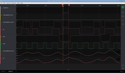
So forgive me if I insist with the resistor mod, I'd much prefer going this way unless we find out it is really impossible to get it working. First let me mention that I had done some tests and they all worked very well, you can even see in the logic analyzer screenshot I put in my essay that the CPU can drive D2 to >4V even when U11 is outputting low. But now I am no longer sure I did those tests with an 8501 CPU! I had two C16 mainboards on my desk, one of which was running on your CPUC16 adapter. I moved things around quite a few times and I really cannot tell what setup I had in my final tests. That was really stupid on my part, I will redo the tests ASAP!
But in the meantime: do you think using a bigger resistor on U11's output (10k?) and/or adding a pull-up resistor on D2 could help having safe voltage levels in all conditions? We need to guarantee two things: 1. The CPU can read the correct level of CST_SENSE when there is no expansion board installed. 2. The CPU can safely read and write high or low from/to an expansion board responding at $FD1x regardless of what U11 is outputting. I guess problems can only arise when U11 and the CPU/board are outputting different levels, when they are outputting the same level, there should be no problem, right?
BTW, the datasheet you linked is for the 7501. Is it possible that the 8501 has better output driving capability?
About the 74654: I replicated that circuit from @dmantione's schematics linked earlier in this thread. He's selling boards with that circuit so I guess they work fine, unless I made mistakes in the circuit, of course. It is supposed to work with both 74654 and 76652. With the 654 the diodes must be replaced bith 0-ohm resistors as far as I understand. Does that look fine?
@gerliczer @MMS: No problem, we can also talk about mouse support here if this card can help with that. But let me say something: I have already designed an USB-to-Amiga mouse adapter (don't look for it, I haven't released it). I can easily recycle some of that code and output whatever you want. So if you can define a suitable mouse protocol, be it serial or whatever you want, I will implement that and we can have USB mice on the C16/+4! And of course I will release all of it openly, in case!
PS: I have now removed the serial signals from the edge connector and pushed the updated board to GitHub.
Re: External User Port for the C16: Let's make it! @SukkoPera I agree with you about using devices that can easy programmed by anyone. Observing your screenshot can be noted that signals are not well represented (example: PHI2 has to be H for the same time at any cycles, 1 or 2 MHz cycles... ). The analyzer represents the logic level by comparing the input voltages with a voltage reference, but if you see the tracks analog representation you can see that the analog bandwidth is too low for sampling this events with accuracy: into the timings evidenced by vertical marker (PHI2=H) there are only 3 sample points, all other is an interpolated "spline".
It's perfectly possible that on your board/cpu/U11/... this modify is wellworking, but this working condition can't be guaranteed for any combination of others board/cpu/U11/... and the screenschot can be a clue, not a proof. It probably always works, but you can only hope for it!
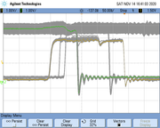
An example of oscilloscope (2G.Samples?) with memory of traces (the signals have to be ALWAYS good...). The tracks represent signals from a C64 board:
7501 has the same specifics of 8501 but they can be not identical (inside theirs specifics).
The 74652 can't work: on parallel port side (PA) the output has to be always active (pin21=L) but the 74652 drive the PA in low impedance mode, so the otputs(A) will drive the inputs(A) independently by the levels of parallel port input pins (external input levels will be lost also in "input" mode).... To avoid this, Commodore used open collector outputs which allow free lines to be driven externally (if out = H) as 74654 can do. "Texas Instruments" produces 4 different types of these devices (74651/2/3/4), some reason there will be ....
During the power up MOS6529B will set to $F the output data (all line will be "input") for avoiding possible conflicts with HW connected with the port, this behaviour is not implemented by 7465X chips.
The 74654 are hard to find (and they are not cheap...), may be that the next solution can be interesting.....
The gates are already implemented on your GAL, it has the "power up" bug (the 273 /CLR can be placed to Vcc and a more common 74LS574 can be used). The RC network extends the DATA BUS driving in READ cycles to meet the 6529B and CPU timings helping the CPU for a correct data reading.
If you want eliminate the "power-up" bug and the 8 diodes..... The perfect replacement of MOS6529B? could be done with a GAL22V10 + 74(HC/HCT)573!
GAL22V10 reset all FF during power up ($0), FF are used for storing the inverted datas so at power up the output data will be $F (all output with collectors open)
Re: External User Port for the C16: Let's make it! @MCes: Don't be fooled, the digital signal you see in my analyzer screenshot is not an interpretation of the slowly-sampled analog data. The digital and analog captures ran at different speeds, analog was at 10 MS/s and digital at 50 MS/s, I think (I use a real Saleae Logic 8). Digital data is sampled with Vih = 1.2V and Vil = 0.6V, which probably do not match the 8501/6529 thresholds, but at least it's sampled much more often than what you see in the analog representation, which should only be taken as an indication (even though 10 MS/s should still be plenty sufficient to sample a ~1 MHz signal...). That misaligned PHI2 cycle still looks odd, though, I concur.
I am now pretty sure I did that capture with your CPUC16 though, which doesn't imply the 8501 will work in the same scenario, I'm aware, I'll test again.
About the 74654, I'll leave the word to @dmantione as that's his design, I really couldn't say anything useful . I'll just add that the "powerup bug" has relative importance in the userport context, as the KERNAL will manually set all pins high at startup (that's the write you see in the analyzer screenshot!), so all that is necessary is to keep everything safe from the electrical point of view.
Re: External User Port for the C16: Let's make it! @SukkoPera FHI2 is H for a half of 2MHz cycle, it's imply that 50MSamples produce 12..13 points but if it's 10MSamples they will be only 2..3 points... I think that the bandwidth is too much limited. Probably the analog probe will sampled at 10MHz and the software will represent the digital out comparing the interpolated line with thresholds at rhythms of (1/50 MHz )nS
From MOS6529B documentation, the level thresholds are to be 0.8V and 2V.
Re: External User Port for the C16: Let's make it! No, the Saleae analyzer samples digital data and analog data separately. The Logic 8 supports up to 100 MS/s for digital, but if you enable analog, that drops down according to how many channels you enable.
Max sample rate for analog data is 10 MS/s in any case and that drops down on its own the more channels you enable.
I will let you know the actual sample rates I used. But again: the digital data you see is NOT a discretization of the analog data you see, it's sampled at a higher frequency.
Re: External User Port for the C16: Let's make it! @SukkoPera https://www.saleae.com/#section-tech-specs "Analog Bandwidth (-3dB) Max 1MHz (depends on the number and type of channels used)" "Sample Rate Max 100MHz (All data is streamed in real time over USB. The maximum sample rates depends on the number of digital and analog channels used)"
It's a good tool for exploring electronics, but too limited to see uncertain behavior so quickly. The PHI2 signal representation is cleary wrong, and it's a standard levels signal.
I don't know when it will be possible, but I can try the "resistor mod" and measure the signals with the digital oscilloscope
Re: External User Port for the C16: Let's make it! As you can see in that page, digital data is reliable up to 25 MHz when sampling at 100 MS/s (but we still have different thresholds). The PHI2 you see in my capture is sampled digitally, but definitely at a lower rate since enabling the analog channels forces you to lower the digital sample rate.
But I understand we need analog data here, I also have a scope with 50 MHz bandwidth, I'll check with that too.
Of course if you can do your own tests too, it will be more than welcome :D.
Re: External User Port for the C16: Let's make it! @SukkoPera USB mouse for Plus/4, C16 and C116? It could be super cool! You know what is the worst thing with original, real RS232 mouses? They became too expensive too We discussed the USB mouse with BSZGG, and definitely it cannot be handled by the Plus/4 alone, simply too fast for us.
Anyhow when you get close to that point (I think we are very lucky at least to discuss this option with you) we need to involve the programmers of the scene about proper memory place and structure for the useful and necessary information.
Frankly speaking, since GEOS, Macintosh, OS/2 or Windows no computer could be taken seriously without mouse support. And we have a home office PC, or at least what the Commodore Marketing team suggested. As we have a missing PotX, PotY input lines, it was not possible beforehand, and without standardized, common approach of the scene it cannot reach certain level of acceptance too.
We have some great tools to be modified/hacked to support his: GEOS+4, Botticelli, Multibotticelli, SVS Calc, TED Screen Editor, just to name few. We should not forget Terra-X from TCFS Maestro, the best candidate for a hack
Re: External User Port for the C16: Let's make it! @MMS: Well, you design the protocol, I implement it . I have no programming experience on 8-bit machines, so I can't help much. I can work on the "other side" (whatever must be done in my adapter) but someone else will have to write the C16/+4 driver. I can add that this is the basic data all USB mice report:
struct MouseReport {
	uint8_t buttons; /**< buttons mask for currently pressed buttons in the mouse. */
	int8_t  x;       /**< Current delta x movement of the mouse. */
	int8_t  y;	   /**< Current delta y movement on the mouse. */
};
USB reports are generally sent at 100-125 Hz. The C16/+4 would sample data at 50/60 Hz, I imagine, so some "accumulation" will be needed, right?
BTW, my adapter is based on a Raspberry Pico and is very cheap to make (~5€), so I think this is worth pursuing .
Just an idea: I think it would be good to base the protocol on the parallel part of the userport, without using the ACIA if possible. I have no idea if the following will work, it's just the first thing that materialized into my mind: if two buttons are enough, we only nee to transfer 18 bits of data. So maybe we could use bits 0 and 1 of as "data selector" outputs to the board, and bits 2...7 as an input from the board:
Sel Bits | Data
   00    | y[5:0]
   01    | x[3:0] + y[7:6]
   10    | LMB + RMB + x[7:4]
   11    | Spare for MMB or wheel data?
This would need 3 "pokes" and 3 "peeks" every time mouse data must be read. Again, no idea if that would be feasible, but hopefully it'll be food for thought :).
Re: External User Port for the C16: Let's make it! @SukkoPera I think that an optimization for your "resistor mod" could be a "time-dependent impedance": not using a single resistor but using a resistor (22K?) paralleled by a capacitor of 100pF.
If CPU is reading: the Data Bus will be in High impedance and the capacitor will drive the D2 line with a transitorial low impedance (resistor has to guarantee the long-term drive) and the correct CST_SENSE will be read,but if any else devices are driving D2 (CPU writing, external cart...) the resistor will represent a light load, and the capacitance would be well tolerated by the device that is driving the D2 line (CPU is specified for driving 130 pF, but remember that parasitic capacitance are present on the board tracks that will be summed with the "100pF")
Re: External User Port for the C16: Let's make it! Thanks @MCes for keeping thinking about a solution! Hopefully I will be able to test that in the weekend.
Re: External User Port for the C16: Let's make it! @Csabo: Wow, you're great! Thanks!
Back on topic: I haven't had the time to test anything in the last few days, but I have completed and ordered the PCBs, after finding a last-minute issue with the pullups of course. I have also ordered boards for other projects which I think you'll like if they work, lol, so stay tuned . I will update the thread after I receive and test the boards.
Re: External User Port for the C16: Let's make it! @SukkoPera Resistor in series between U11 out to D2 drive, CPU= genuine MOS8501: I tried the 100pF+22K and it was bad, so I tried (without capacitor) a variable resistor and I found 2.2k as value that start to not read well the keys on tape unit, so the value can be chose in 1k, 1.2k, 1.5k.
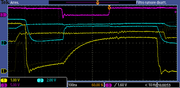
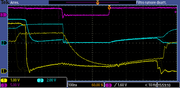
I tested the heaviest: 1k. into the pics you can see: ch3 (violet) the U11 enabling (5V/div.) ch2 (blue) the U11 out (2V/div.) ch1 (yellow) D2 (1V/div.)
Note: 1) The U11 enabling end 20nS after PH0 falling edge 2) CPU read well if data is stable from 40nS before to 40nS after the FH0 falling edge
CPU read well the tape keys not pressed (U11 out =H):
CPU read well the tape keys pressed (U11 out =L):
For testing the writing conflict I use the spare NOR gate into U12 feeding it with "R/W" and "U11 enabe" signals: the NOR out will be H only when the CPU ask for a write operation on $FD1X (note: NOR delay 15nS)
Re: External User Port for the C16: Let's make it! Great work @MCes, thanks a lot! So, if I understand correctly, replacing the 2.2k resistor in my instructions with a 1k one is all I need to do? Is U11 able to withstand the current it would have to source/sink when it's trying to drive the line at the opposite level wrt the CPU?
EDIT: A little update!
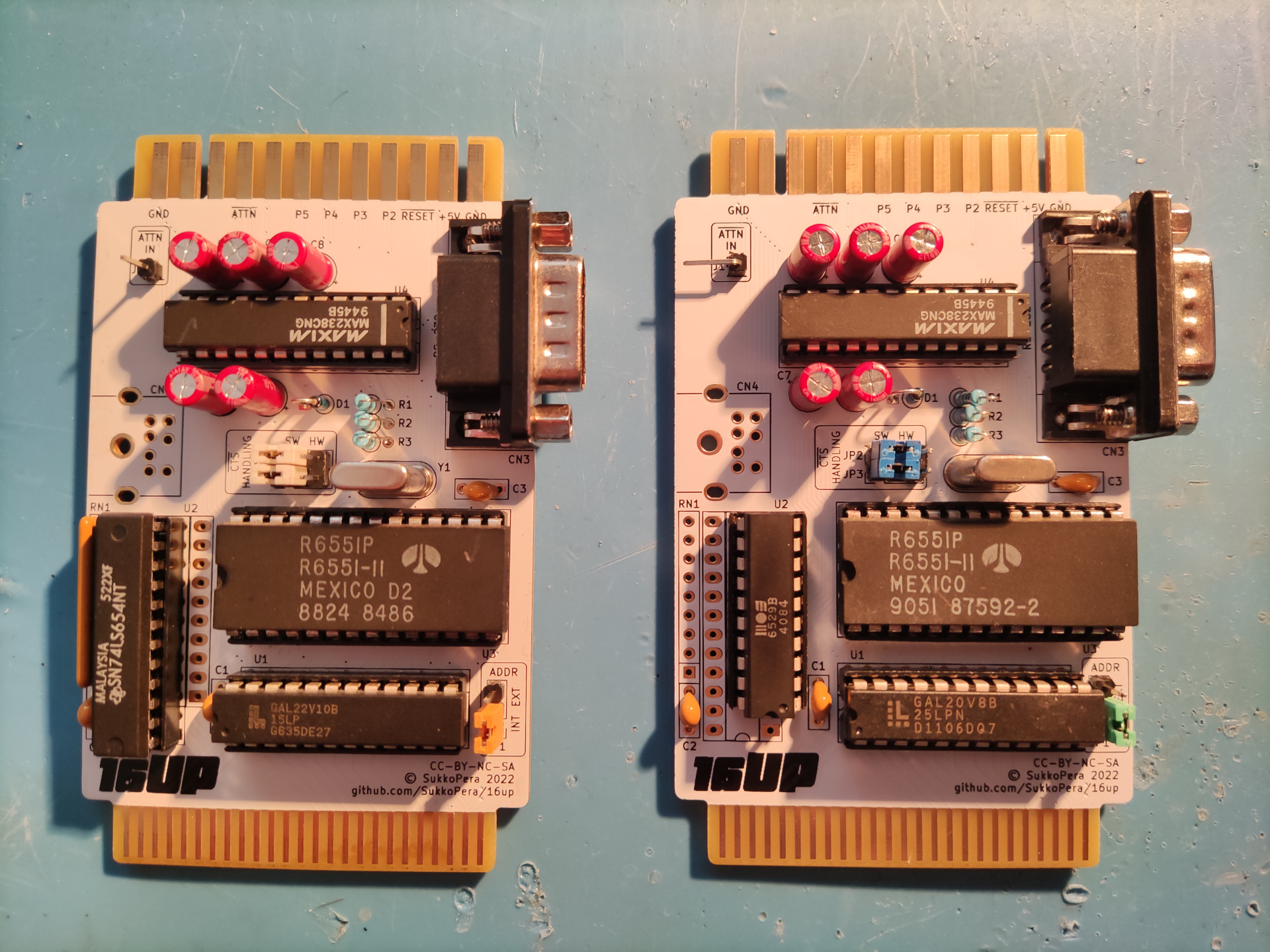
So, I have finally received the boards. The manufacturer screwed up a bit but they are usable for testing:
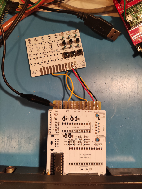
I started testing the parallel port with an original MOS 6529 and it seems to work well. I had designed a second attachment board that would make the testing very simple, but unfortunately I screwed that up myself by using the wrong connector pitch. Not a big deal though, as I cannot seem to find my stash of edge connectors so I had to resort to unorthodox manners anyway:
I only soldered and wired D0/1/2 as they're the ones that might be problematic. This C16 has @MCes's CPUC16 inside and the 2.2k resistor mod: it's working flawlessly, both when reading and writing from/to the port, regardless of whether a key is pressed on the Datassette or not.
More testing is necessary (most importantly on a stock machine with just the 1k resistor mod) but the first results are encouraging :).
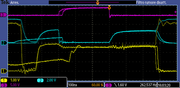
2ND EDIT: Did more testing on a stock C16 with an original 8501 and the 1k resistor mod as recommended by @MCes: everything seems to be working fine! Here's some scope traces:
Legend: - Blue is U11/MOS 6529 /enable - Yellow is D2 - Pink is output from U11 pin 8
Everything looks good to me and with safe enough margins so far! :) Tomorrow I will make some tests with the CPU writing to the bus.
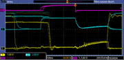
3RD EDIT: And here's CPU write tests, where dark blue is R/W:
Looks good enough to me, but I would like @MCes's opinion on it! :)
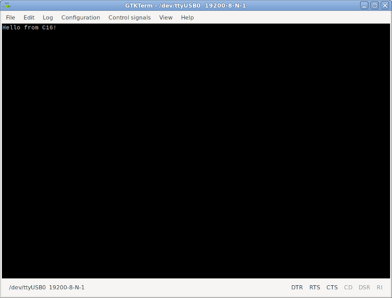
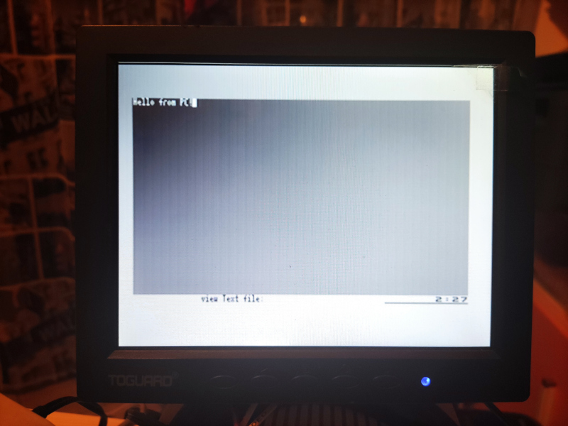
4TH EDIT: Since the parallel port tested fine, I moved to testing the serial port. I found out that /CTS needs to be inverted when handled in software, which will need some changes in the PCB, but I have already tested those and actually they even improve the use experience, as they will remove the need to move a jumper when using the serial port. Other than that everything seems to working fine, I tested all signals one way or another and they are all good. Then I connected the C16 with a PC through a null-modem cable and I was able to communicate correctly at 19200 bps:
I will update the PCB soon and then I guess we're good! A long-time dream finally comes true! ;)
5TH EDIT: I have updated the PCB and fully released the project. There is no official release of the updated PCB yet, I need to test the 6529 replacement circuit first :).
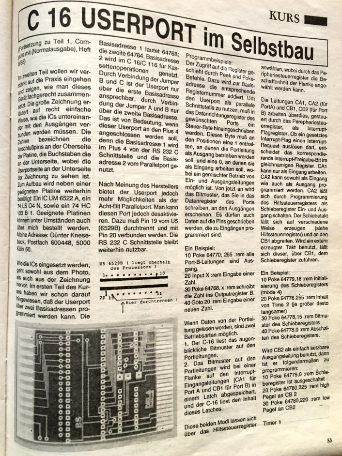
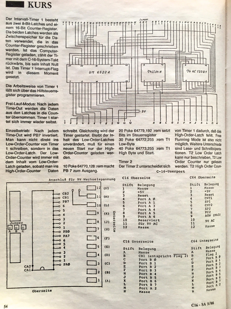
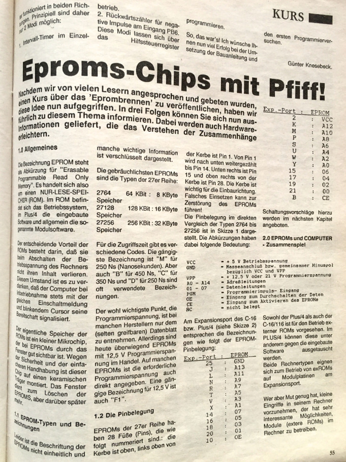
Re: External User Port for the C16: Let's make it! I know I am a bit late to this party ... and I have really no hardware knowledge ... but I remember there was a userport for the C16 in the past. Here are some fotos from the old text in the german "Compute mit - C16, 116 & plus/4 Sonderheft":
Re: External User Port for the C16: Let's make it! Right, but that is a different beast: it's based on the VIA, the port expander chip used in the VIC 20 and earlier Commodore machines (the precursor of the CIA used in the C64). It can definitely be used to make a User Port (and probably an even better one) but that one would not be compatible with the +4 User Port, requiring software to be written ad-hoc.
EDIT 23/11: Some time has passed and I have finally managed to hunt down some 74ALS652's, 654's and BAT43's in order to test the 6529 replacement circuit. The 654 works perfectly, unfortunately it is pretty hard to find. The 652 is much easier to find (and a variant of it is even still in production, though not in the DIP package) but unfortunately the replacement circuit doesn't seem to work well in this case.
I have tested with BAT43's and also other diodes and the general behaviour is that the circuit works perfectly when pins are used as outputs, being able to pull a load both high and low, but pins always read as high when they are used as inputs.
I have also tried reversing the diodes (since I had originally got them in the wrong orientation, maybe...) and that sort of reverses the behaviour: pins now work perfectly as inputs but are unable to pull a load low when used as outputs.
So this is probably what @MCes was alluding to some posts ago, but then if the same circuit works in Daniel's 6529 replacement, I must have got something wrong in my replica. I have now triple-checked it but I can't find anything that is clearly wrong.
Re: External User Port for the C16: Let's make it! @SukkoPera 74ACT652 and 74ACT654 are two different chips, 74ACT652 can't work properly, 74ACT654 can work (no diodes and R=3.3K).
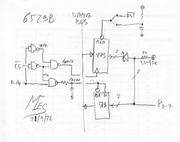
If you want a schematic for a 6529B replacement ("power on" features included) that doesn't need of any PLD try this:
IC "D" generate the signal "/R" and "/W" (it can be integrated into an already present GAL). RC net delay 30..50nS the "/R"signal for better bus timings match. When /R go to L than the input port information is latched for a safe CPU reading and the buffer "E" feed the DATA BUS. At power on another RC network reset to $0 the "B" register that memorize data in reversed form, so a $0 into "B" will be reversed to $F by 8 open collector inverter ("C"), another chip ("A") reverse the data from the bus for a correct register feeding.
Re: External User Port for the C16: Let's make it! @MCes: the difference between the '652 and '654 is clear to me, but Daniel is selling a full 6529 replacement that he claims can work with both. He kindly provided the circuit for that and that is what I have implemented in my board. So, either I missed something or his board doesn't work properly with the '652, in which case I'm sure he'd like to know .
I will have a look at your proposal, but at first sight I don't have space on my board for all that stuff.
@Frenetic: could you please summon Daniel here? Hopefully he will be able to shed some light.
Re: External User Port for the C16: Let's make it! @SukkoPera The kit that Danial is selling is composed by a 74ACT654, 8 resistors and 8 "zero Ohm" jumper (at the diodes places, I suppose): exactly what I told in the precedent post. I analyzed the 74ACT652 behaviour and theorically it can't work properly, you tried in practice the 74ACT652 and it doesn't work where the 74ACT654 work.... Ask yourself a question and give yourself an answer....
Referring at my last post, into schematic the chips A,B,C,D can be implemented into a GAL22V10 for lowering the PCB surface of this solution, but if the "power on set" behaviour is not needed a simpler replacement can be done.... I suggest to read another time a previous post:
-------------------------------------------------------------------------------------------------------------------------------------------------------------------------------------------------------------- The 74652 can't work: on parallel port side (PA) the output has to be always active (pin21=L) but the 74652 drive the PA in low impedance mode, so the otputs(A) will drive the inputs(A) independently by the levels of parallel port input pins (external input levels will be lost also in "input" mode).... To avoid this, Commodore used open collector outputs which allow free lines to be driven externally (if out = H) as 74654 can do. "Texas Instruments" produces 4 different types of these devices (74651/2/3/4), some reason there will be ....
During the power up MOS6529B will set to $F the output data (all line will be "input") for avoiding possible conflicts with HW connected with the port, this behaviour is not implemented by 7465X chips.
The 74654 are hard to find (and they are not cheap...), may be that the next solution can be interesting.....
The gates are already implemented on your GAL, it has the "power up" bug (the 273 /CLR can be placed to Vcc and a more common 74LS574 can be used). The RC network extends the DATA BUS driving in READ cycles to meet the 6529B and CPU timings helping the CPU for a correct data reading.
If you want eliminate the "power-up" bug and the 8 diodes..... The perfect replacement of MOS6529B? could be done with a GAL22V10 + 74(HC/HCT)573!
GAL22V10 reset all FF during power up ($0), FF are used for storing the inverted datas so at power up the output data will be $F (all output with collectors open)
-------------------------------------------------------------------------------------------------------------------------------------------------------------------------------------------------------------- @SukkoPera: a little note: the parallel port solution based on 74LS652 appear to be wrong, I think that it has to be 74(..)654: portA output (Parallel port) open collector, portB (DATA BUS) 3State, also the diodes on P0..7 have to be removed.
Re: External User Port for the C16: Let's make it! Hello,
I have read up on the discussion between 652 and 654 and I think the point against the 652 is valid. I have indeed designed my replacement to be compatible with both 652 and 654, tested a bit with both, but then never worked with the 652 again. I have sufficient 654 chips, so there wasn't much point until now to look into the 652 topic again.
I'm puzzling a bit with the idea wether a pulldown resistor between diode and input can fix the issue, but then you have a pulldown before the diode and pullup after the diode, it will likely become a mess...
I am not sure I agree wether I agree with the bootup problem: 1 - The 6529 has no reset pin. This means that after a reset, the state of the 6529 should be considered unknown. 2 - The data sheet of the 6529 explicitely recommends that it is interfaced with open collector output devices, likely because of these issues 3- Even in case a push-pull interface is used and a conflict happens, generally no terrible things happen because of the resistors the chips have in the output drivers, and the conflict will be there for a very short time, as the KERNAL resets to input very quickly after reset.
Therefore, in lack of sufficient 654, a two chip solution should work. My first thoughts would be 377+541, but the schematic with 273+573 looks good as well. Indeed you can also use a GAL, but it looks overkill to me.
Re: External User Port for the C16: Let's make it! Thanks Daniel for getting back to this thread.
I don't think there's any way to get the '652 working properly, as it has push-pull outputs and there's no way to cleanly bring those down then they are outputting a high level (this is probably what @MCes has been saying since the beginning). Maybe we could find a way to have it switch to input mode instead of outputting a high level (the pull-ups would still make up for the high level) but that won't work in the general case, since we could only do that for all pins at once, while the 6529 can have inputs and outputs pins at the same time.
Well, at this point I think I'll just remove the diodes and only keep the possibility to use the '654 as replacement. Theoretically, the '654 is still in production, at least in the SOIC package, so that shouldn't be too bad a choice. Digikey apparently also still has 1000+ pieces of the DIP version, even though they are not cheap and must be bought in packs of 65.
The power-up reset feature of the original 6529 is not crucial for this application. The KERNAL writes $FF to $FD10 very soon at startup, probably to cope with the lack of a reset signal in the 6529, as you say. This wouldn't happen when the board is configured to respond to $FD70, but that will require some custom treatment anyway, so it's not a big deal either.
Re: External User Port for the C16: Let's make it! @SukkoPera: the 6529 can have inputs and outputs pins at the same time Is that so? I'm not sure, but either I misunderstand you or you are mistaken. 6529B has no data direction register. All pins either read or write depending on the R/W input. AFAIK.
Re: External User Port for the C16: Let's make it! We are both right . What I meant is that the 6529 can be driving P0 low as an output, for instance, and reading data from P1 (which means it must leave it float, which corresponds to "driving" it high) at the same time. If we make the replacement '652 switch to input mode in order to sort-of-fake the Open-Collector behavior and do the latter, that will switch the whole port to input mode and it will no longer be able to drive P0 low.
A bit convoluted, yeah, but I think it makes sense .
Re: External User Port for the C16: Let's make it! @gerliczer the 6529B implements something that Intel 805x people generally refer to as a "quasi bidirectional" I/O port, see: IO Pins Ports and Circuits of 8051 Microcontroller, page 2, Port 1 (and 2,3). In short, data reads come directly from the I/O pins, data writes are stored in an internal latch, which (the latch, that is) feeds the I/O output drivers. Until this point this would just be an unidirectional (output) I/O port, whose output state can be read back. The trick is, that the I/O drivers are asymmetric, that is, they produce strong "low" but weak "high" levels. (In the case of the 8051, this "high" level is also produced by a static pullup resistor, not a controlled high-side driver mosfet). Now, if you set some output pin to "high" (1), and pull the resulting "weak" high level "low" by some external device, the "low" state will be reflected by the data read from the port (which, as said, reflects the I/O pins' states directly). This is how the 6529B can be a bidirectional port (where also every bits can be freely used as inputs or outputs individually), even with no data direction register used.
Re: External User Port for the C16: Let's make it! My thoughts about getting the 74x652 working were as follows:
https://i.postimg.cc/gcMc60V3/afbeelding.png
i.e. the diode correctly emulates open collector in case of a output, but in case of an input, it prevents the external driver to pull the input down. The extra pull-down resistor in front of the diode will fix this. I have decreased the resistor value a bit in the example, because they are now pulling against each other.
Now, 68K is a rather large resistor value to connect to an input. It might be too much for a chip with bipolar logic, because for those you must actually pull a current to keep the input low and with 68K it might be too low. It may work better for chips with (C)MOS logic, because there the voltage on the input is what counts and 68K will get to a low state. However, it may still pull down at a rather slow pace. And the chip must not have an internal pull-up. If it has an internal pull-up, this trick will fail of course.
Re: External User Port for the C16: Let's make it! I'm still an amateur with this forum, it says I should drag/drop the image, but that just gets me the URL of the image in plaintext
Re: External User Port for the C16: Let's make it! OK Gents, I'm officially completely lost. Electronics is obviously way above my head. I still don't get it how you do a read operation on a 6529B without an actual read operation, but that's all right. I believe in you being right without further questions.
Re: External User Port for the C16: Let's make it! I'll try to be as short and clear as possible: 1. You decide which pins shall be outputs and which shall be inputs. 2. You write a value to write to the port that is made up as follows: - If a pin is an output, you set the corresponding bit high or low as you want the level to be; - If a pin is an input, you set it high (1). 3. You read from the port: you'd expect to read back what you just wrote, but here's the key: if a pin that was written high is actually being shorted to ground by whatever you connected to it (this is electrically safe with open-collector-style outputs), the corresponding bit will be set to 0 rather than to 1, reflecting the actual status of the pin.
Re: External User Port for the C16: Let's make it! The secret to the 6529 is its "Weak pull-up" behaviour: If you set it high (transmit a 1), the line is pulled up with +- 8 kOhm. This resistance is low enough for reliable communication as an output, but high enough so that it can easily be overridden by a transmitting device when used as an input.
As long as a pin is high (you are sending a 1), you can also read from the pin.
Re: External User Port for the C16: Let's make it! Well, here's V2!
UPDATE 21/01/2023 V2 boards have arrived and have been assembled and tested. Everything works as it should, so I have released it. Thanks to all those who helped!
In the meantime, I have found out that some old UserPort to Centronics Port cables use both the 8-bit parallel port and a few control signals of the serial port. These won't work with this adapter. I think the alternative Centronics cable designed by Solder only used the parallel port instead. Can @siz or anyone else who has one please provide pictures of the internals so that we can replicate it?
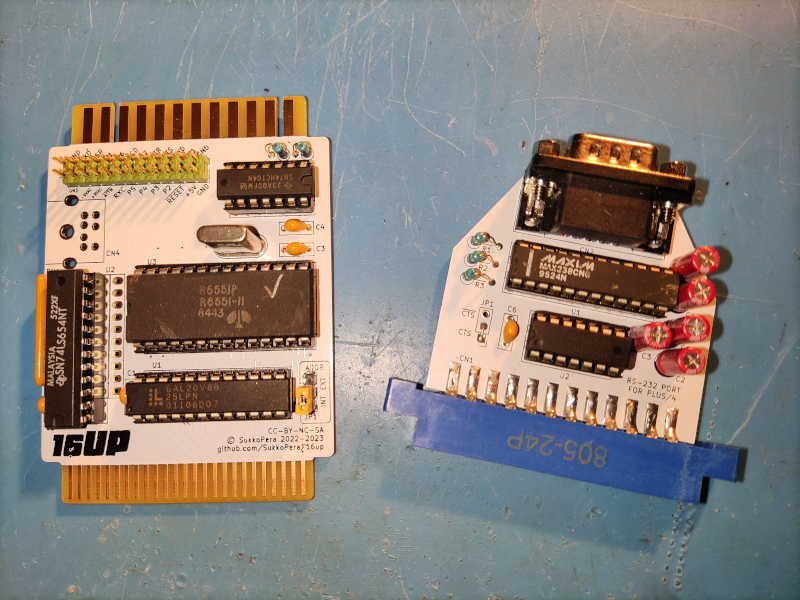
UPDATE 05/04/2023 I have some news about this project: the MIDI card we developed in another thread uses both the parallel and serial signals, so it was about time to make this:
This is 16UP V3, which features an 87.5% Plus/4-compatible user port! All signals are now available on the edge connector right where they should be, except /ATTN (is there anything that uses that?) and the 9VAC power rails. These signals can still be provided through the pin header, which I extended to all signals in order to also facilitate scoping and experimentation.
As you see, I also developed its ideal companion, i.e. a board that adds the now-missing RS-232 serial port. This does not require 9VAC power, so it works right away and can also be used on the Plus/4, of course!
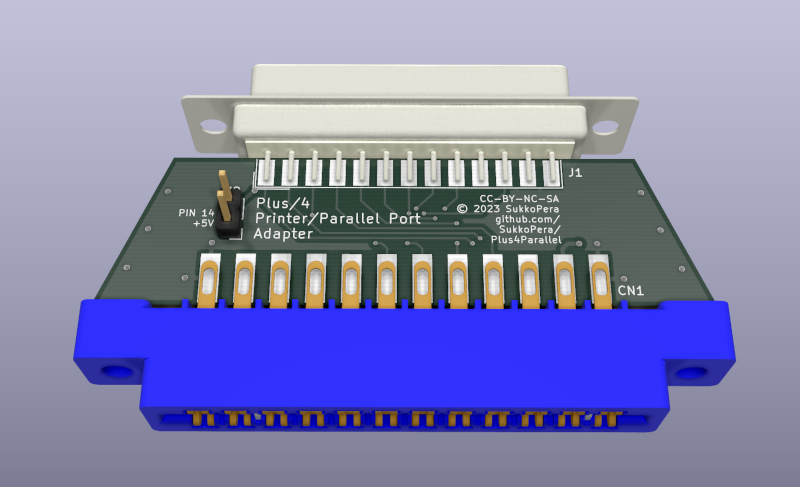
I have also developed a Centronics/Parallel Printer adapter, but I haven't got it manufactured yet. This would be the adapter that I mentioned in the Covox thread which could make it work:
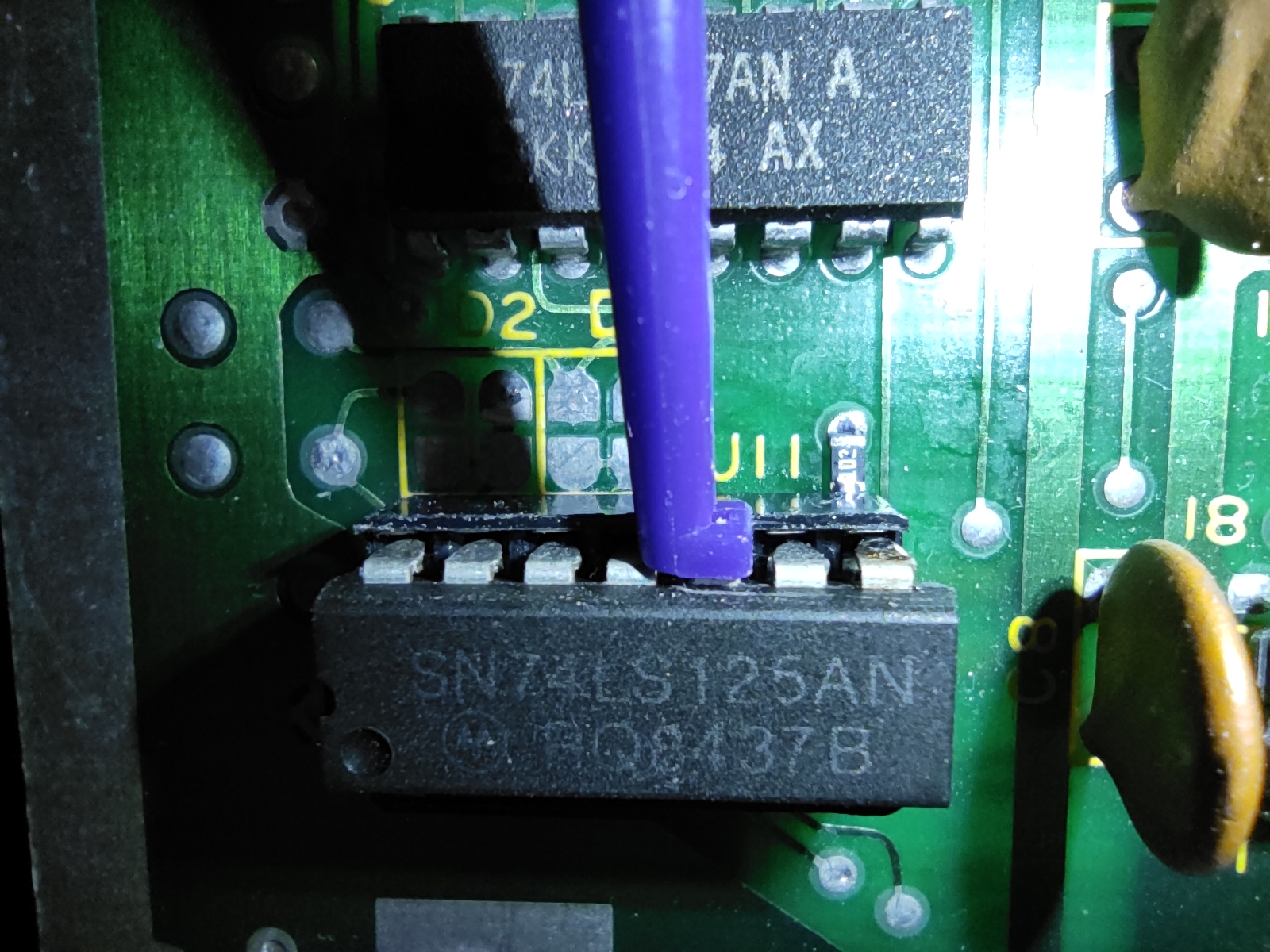
Finally, I have found a way to make the internal resistor mod safer and more discreet:
I used a 0805 resistor: one side is soldered to the via right above U11 pin 8 (which is still D2), while the other one is soldered to the leg of the socket, which no longer connects to its designed hole, of course. This makes the whole thing really solid and pretty invisible :). (Ignore the clip, it's for the 256kB RAM expansion)
All things will be released ASAP.
ADDENDUM 06/04/2023: Here's a quick video showing that after the mod all parallel port bits can be individually toggled on and off (and another board I made, the UserPort Tester):
Re: External User Port for the C16: Let's make it! Good evening, some time ago ( June 19, 2020) I had already created a Dreammodem board with Userport and Wi-Fi modem on board. With the parallel output I had driven an SVI-2000 arm. The project is already functional and stable, but I still have to run some last tests on the card and the completion of the management software. This is the link of the presentation I made in an online evening of the association I belong to:
Re: External User Port for the C16: Let's make it! @DreamTronic: go on Francesco, looking forward for a very first show of the final release behind the boundaries of the Granducato!
Re: External User Port for the C16: Let's make it! Regarding that Parallel port,
If it was ever possible as it would need software to talk to it..., Iomega Parallel 100MB Zip Drive. Parallel ports are generally slow though and normally suck the guts out of the cpu. On a Win98 PC these things were almost as fast as the first gen usb SD cards of that time. Perfect for small files any way. But yeah, if it was at all possible it "may" have the potential for faster loading times than a floppy drive.
Re: External User Port for the C16: Let's make it! I don't know if it's doable at all. Only the 8 data bits and the /STROBE and /BUSY signals are handled. Maybe 1-2 more signals could be added but no more. I don't know if it's enough for such a driver/device.
I know that a couple of people have already bought the Plus4Parallel board despite it being untested. If it's anybody from this forum, can you please let me know whether it works properly and/or if anything needs to be changed?