| Posted By

Retroshire
on 2020-06-08
04:29:40
|  Information about PCB difference, revisions of IC, historics Information about PCB difference, revisions of IC, historics
I am looking for information about the different PCB's and revisions of the Commodore 16. Are there any differences, quality's etc. What is the difference between the PCB with white printing and yellow printing? Also production information from CPU 7/8501 and TED 7/8360. Are the later productions better or worse? Are there any differences in country of production?
|
|
Posted By
MMS
on 2020-06-08
12:30:01
 | Re: Information about PCB difference, revisions of IC, historics
I am not a HW expert, but in some previous post it was mentiuoned that the 8501 R3 (sometimes pop up on different sites) are the latest, improved version of the MOS production process, and expected to be the most reliable one. (but we do not have any statstics of the failed CPUs datecode, etc)
|
|
Posted By
unclouded
on 2020-06-09
18:59:35
| Re: Information about PCB difference, revisions of IC, historics
I am very interested in this. If you find things, where will you keep them? here? I just had a PLA fail. 251641-02 with week code 3884. Powered up after years in storage, video for one second then no video.
My C16 boards are "PCB NO 251789-01 REV A" or "..REV B". Here is one:
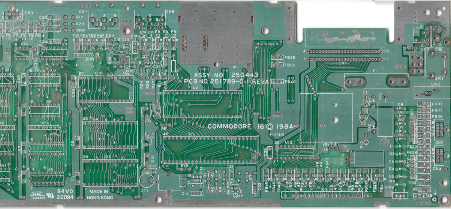
It's clipped on the left sorry. Didn't all fit in my scanner.
I read here that Commodore recommended adding clamping diodes to some external lines to prevent voltages much below 0V or above 5V from being applied to the chips:
I would love to know if any boards were ever made with such improvements or if they were just patched instead.
IIRC, 7XXX is HMOS and 8XXX is HMOS-II process. From https://en.wikipedia.org/wiki/Depletion-load_NMOS_logic#The_HMOS_processes "According to Intel, HMOS-II (1979) provided twice the density and four times the speed/power", so maybe the 8XXX just produced less heat?
|
|
Posted By
MMS
on 2020-06-10
17:52:16
| Re: Information about PCB difference, revisions of IC, historics
It is rather interesting topic.
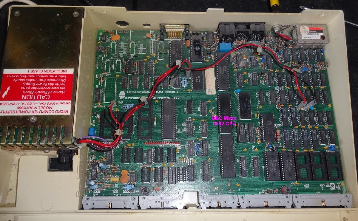
BBC Micro used a 6502 CPU with 2MHz speed, and it was quite reliable.
The least reliable part in BBC was told to be the switch mode PSU.
It used 480mW at 2MHz. AFAIK the 7501 (based on the datasheet) requires 125 mA, at 5V it is 625mVA at 2MHz.
I do not see the benefits of the HMOS process
So the 6502 was reliable @2MHz.
But it had almost 5cm free space above CPU, which is not the case even in C16, and evidently not in +4.
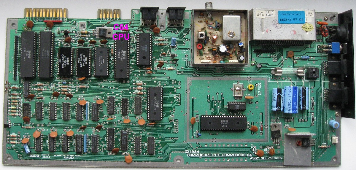
So it may initiate some questions, if the main problem with the 7501/8501 CPUs are with the higher clock rate versus C64's 6510 (0.98MHz) or due to the fact that 7501/8501 has much less space and air ventillation, even compared to C64's 6510 CPU? As you can see, the C64's 6510 (@0.98MHz) is posisioned very close to the tape connector opening, so the CPU could get some fresh air via that opening.
BBC Micro's stable and reliable 6502 was also positioned to the center of motherboard in the same way as the 7501/8501 in C16.
But the 2Mhz 6502 may have a better ventillation than C16's 7501, not to mention Plus/4.
|
|
Posted By
Retroshire
on 2020-06-13
08:54:05
| Re: Information about PCB difference, revisions of IC, historics
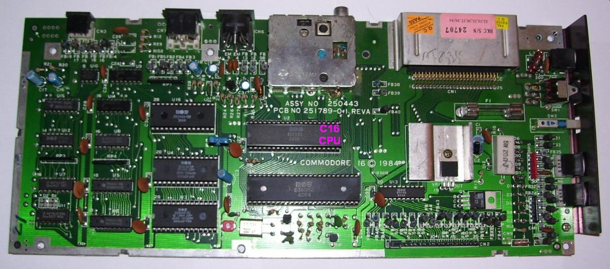
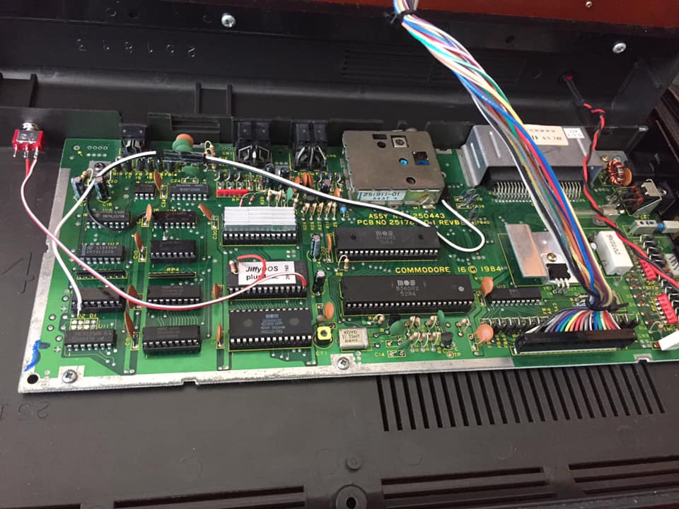
In fact I have found some variation in my PCB's. This one has diods (above PLA):
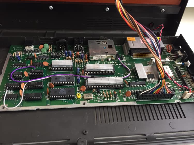
This one has not:
|
|
Posted By
unclouded
on 2020-06-11
05:42:07
| Re: Information about PCB difference, revisions of IC, historics
>I can not paste a picture nor add a file, how did you?
When you post a reply, above the text boxes there is a link to "new Site Uploader"
|
|
Posted By
Retroshire
on 2020-06-13
08:50:58
| Re: Information about PCB difference, revisions of IC, historics
I don't see such a message on my screen >> thanks Zoltan, this worked.
|
|
Posted By
MMS
on 2020-06-13
09:25:11
| Re: Information about PCB difference, revisions of IC, historics
It is at "Features" menu. First you need to add your reply. Submit it.
Upload the picture. It should be Jpg and less than 2MB.
Copy the link to clipboard. Go back to forum, edit your comment and add the link.
Certainly there is an easier way, but I am noob level and for me it works 
|
|
Posted By
Retroshire
on 2020-06-13
09:13:42
| Re: Information about PCB difference, revisions of IC, historics
Do these diods make a lot of difference? Is it for protection sake or another reason?
|
|
Posted By
unclouded
on 2020-06-13
18:16:20
| Re: Information about PCB difference, revisions of IC, historics
I'm not an EE but I think they're clamping diodes. Those diodes with their cathode (the line not part of the triangle) wired to +5V will be forward biased if their anode is above 5.7V (conventional current will flow from the anode "down" to the cathode as long as the voltage difference exceeds the diode's junction voltage of ~ 0.7V). If there were a 100V spike on the input pin (perhaps from static discharge?) then the diode will dissipate the power (as a brief heat increase?) so that the 100V is not applied to the sensitive ICs for long. The diodes wired to GND are the same but harder to think about because the conventional current flows from GND "down to" -100V or whatever the spike is.
|
|
Posted By
Retroshire
on 2020-06-14
02:09:09
| Re: Information about PCB difference, revisions of IC, historics
Thanks Neil, so when futureproofing your system, this will be a smart thing to do. I wander why they did it only with the Serialport and not to cassette- and joyports. Joystick adapter nowadays often have a femalepart with iron on it. ESD is easily getting thru.
|
|
Posted By
MMS
on 2020-06-14
04:38:31
| Re: Information about PCB difference, revisions of IC, historics
Exacly. Although ESD point of view the on and off condition does not count, the joystick ports are more often touched than IEC, and kids frequently swapped joystick ports when the machine is in ON condition. Protecting TED from this possible effect (especailly as joystick ports directly driven by TED) could be more important, than the IEC port.
Solder made a TED protector circuit for that, but that diagrma seems to be lost. The PCB that may protect the joystick ports from ESD is linked beforehand, that is based on Levente's design. I do not know, if Solder's and Levente's design is similar or a completely different approach.
|
|
Posted By
Retroshire
on 2020-06-14
06:48:46
| Re: Information about PCB difference, revisions of IC, historics
I like you contribution here and will link it to this thread:
forum/40206
|
|
Posted By
MCes
on 2020-06-15
03:41:53
 | Re: Information about PCB difference, revisions of IC, historics
If you have a 1540 or 1541 drive:
prepare on your table your Commodore systems (computer, monitor, 1540 or 1541 drive, ecc..) and plug ALL cables (computer to TV, psu to computer, 220Vcable to 1540/1541, ecc...) but DON'T PLUG THE SERIAL CABLE!
Use a multimeter (AC voltage) for measuring the potential difference between the computer ground and the ground of 1540/1541, I think that it will be interesting....
|
|
Posted By
MMS
on 2020-06-15
17:05:08
| Re: Information about PCB difference, revisions of IC, historics
Off
MCes: well it may also happen if they are not plugged into the same extender, especially if you have 3 phases (380V) in your house and they are using the different phases (zero point shift).
I saw similar thing personally at a hostel, within the same room there was 40V of difference between the two wall socket's ground. Actually the EPSON printer made a small spark sound when hot plugged to the PC's centronics port.
|
|
Posted By
MCes
on 2020-06-17
02:52:57
| Re: Information about PCB difference, revisions of IC, historics
The safest way to connect a 1540/1541 is to connect the serial cable as first (when the 220V drive cable is unconnected, not only the drive switched off. I advice that also the computer has to be unconnectet: PSU, TV, ecc...) because it exclude that the two devices may have different ground references.
Remember that commodore C16, PLUS4, ecc... have no ground references, so they acquire the reference of the plugghed devices (as the TV.....and its antenna cable ground, also during a thunderbolt storm...) that can be not having a ground references: an accumulator of static current that can be discharged during the serial bus cable connection!
The pins of the serial cable have all the same length, in some modern connector the reference (ground) pin is longer than others because it has to be the first that have to be connected when you press the plug to connect it.
The serial cable plugging can create an instantaneous bridge with DATAs line (and no ground) between two sides that have a lot of voltage differences, and without protective diodes the computers port will die...
But also the 1541 side has the same problem on the same lines, but..... it can't have the diodes!!!!!!!!
Otherwise when the 1541 is switched off the "upper" protective diode (connected to internal 1541 +5V line that now is off= 0V) will pull down the data/reset lines on the serial connector with the effect of constantly reset all peripheral devices on serial net, and also resetting the VIC20 and the first series of C64 (other computers have two different reset line: the internal one and the external one).
|
|
Posted By
Retroshire
on 2020-06-17
06:20:33
| Re: Information about PCB difference, revisions of IC, historics
Thanks Massimilano for your suggestions. As I understand the serial ESD problem can not be solved with diods, not because of the computerside, but because of the 1541 side.
Is it better/saver to use ungrounded wall outlets?
|
|
Posted By
MCes
on 2020-06-18
03:31:50
| Re: Information about PCB difference, revisions of IC, historics
The safest way to connect a 1540/1541 is to connect the serial cable as first (when the 220V drive cable is unconnected, not only the drive switched off. I advice that also the computer has to be unconnectet: PSU, TV, ecc...) because it exclude that the two devices may have different ground references.
--------------------------------------------------------------------------------------
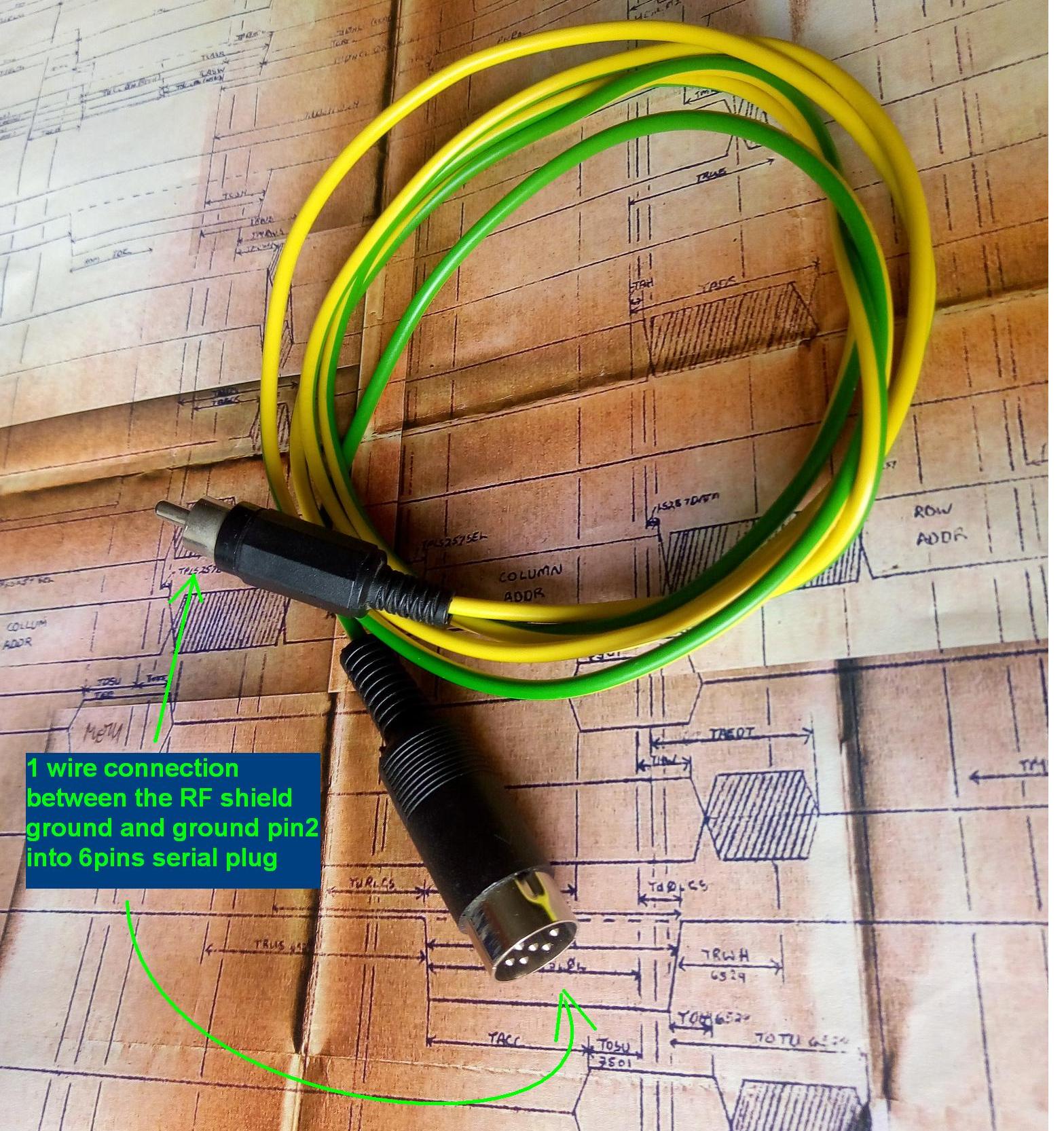
When I have to connect my 1541 to my computer: before to connect them I use to make them equipotential using an equipotential cable.
This is a 1 wire cable that on a side is connected to the shield of RF (TV) plug (the ground of the computer) and the other side is connected via 6pins serial plug only to the pin 2 (ground of the external devices).
When this "ground bridge" is plugged it will possible connect the serial cable without any kind of problems (plug the computer side first: it has the protective diodes that can be useful to discharge the bodys static potential of person that is plugging the cable).
After the serial cable is plugged the "ground bridge" has no task (ground connections are also inside the serial cable): now you can unplug it or let it in connected ready for the next serial cable plugghing....
(normally the computer has the RF TV connector free, also the serial external devices have 2 serial connectors, so the "equipotential cable" connection is without trouble)
|
|
| |
Copyright © Plus/4 World Team, 2001-2025. Support Plus/4 World on Patreon |